The Fundamentals of a Plate Heat Exchanger Diagram
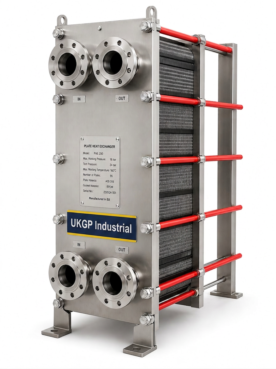
A typical plate heat exchanger diagram displays the intricate arrangement of corrugated metal plates clamped together within a structural frame. For UK engineers, these drawings are more than just schematics; they are blueprints for energy efficiency. The diagram illustrates how the primary and secondary circuits interact through thin stainless steel or titanium walls without ever coming into physical contact. Each plate features four ports, which serve as the entry and exit points for the two fluid streams, often arranged in a counter-current flow pattern to ensure the highest possible temperature gradient across the heat transfer surface area.
When reviewing a detailed plate heat exchanger diagram, you will notice the chevron patterns on the plate surfaces. These are not merely for structural rigidity; they are designed to induce turbulence in the fluid flow even at low velocities. This turbulence is critical for preventing the stagnant boundary layer that often inhibits heat transfer in traditional shell and tube designs. In the context of BSRIA BG29/2021 pre-commissioning cleaning, understanding this internal geometry is vital, as it highlights why maintaining water quality is paramount to preventing the narrow gaps between plates from becoming blocked by debris or scaling during operation.
Integrating a high-quality UKGP plate heat exchanger into your plant-room design ensures you are utilizing a component built for long-term reliability. We offer both gasketed and brazed units, ranging from DN20 to DN300, which are sized specifically from your full thermal specification to ensure they meet the unique demands of your project. Each unit comes with a 2-year warranty and a manageable lead time of 4-6 weeks, providing contractors and procurement leads with a dependable solution that matches the theoretical performance shown in any technical plate heat exchanger diagram provided during the early design and tendering stages.
- Visualisation of primary and secondary fluid port entries
- Identification of chevron patterns for Reynolds number optimisation
- Clamping bolt locations for gasketed plate maintenance
- Counter-current flow orientation markers
- Clear distinction between heat transfer area and distribution areas
Flow Path Dynamics and Counter-Current Heat Transfer
In any professional plate heat exchanger diagram, the flow paths are typically indicated by contrasting colours to differentiate between the cooling and heating mediums. The most efficient configuration is counter-current flow, where the two fluids enter from opposite ends of the plate pack. This arrangement ensures that the cold fluid meets the hottest part of the warm fluid as it leaves, and vice versa. By maintaining a constant temperature difference throughout the length of the flow path, engineers can achieve a much higher temperature approach, allowing for more compact units that still deliver high-capacity thermal exchange in restricted plant-room spaces.
CIBSE guidelines often reference the thermal efficiency of these units, particularly when integrated into Low Temperature Hot Water (LTHW) systems or District Heating Networks (DHN). A plate heat exchanger diagram will show how the fluids are distributed across the entire width of the plate through the distribution area. This ensures that no 'dead zones' exist where fluid becomes stagnant. Stagnant zones are not only inefficient but can also lead to localised corrosion or the accumulation of biological films, which is a major concern for facilities managers operating under BS 8552 water quality monitoring standards in commercial buildings.
Choosing the right flow configuration often depends on the specific pressure drop requirements of your system. If the diagram indicates a single-pass arrangement, all fluids pass through the length of the plate pack once. For applications requiring exceptionally close temperature approaches, a multi-pass arrangement may be shown on the plate heat exchanger diagram, though this increases the complexity of the piping and the internal sealing. Consulting with a specialist like UKGP allows you to receive a bespoke thermal sizing that balances these flow dynamics with your budget and space constraints, ensuring your system performs exactly as the schematic intended.
- Maximising the LOG Mean Temperature Difference (LMTD)
- Single-pass vs multi-pass flow path considerations
- Fluid distribution across the plate width to prevent dead spots
- Pressure drop management via plate corrugation selection
- The role of turbulence in self-cleaning properties
Protecting the Plate Pack with Air and Dirt Separators
While a plate heat exchanger diagram shows the idealised flow of clean fluids, the reality of UK heating systems often involves the presence of magnetite, scale, and air. These contaminants thrive in the narrow channels depicted on the diagram. If a system is not properly protected, the fine gaps between the plates can act as a filter, trapping debris and significantly increasing the pressure drop across the unit. This not only reduces the thermal efficiency but can also cause premature failure of the gaskets or the plates themselves due to localised erosion or corrosion under deposits.
To mitigate these risks, it is standard practice for M&E contractors to install robust filtration and separation equipment upstream of the heat exchanger. This is where British Standards and BSRIA recommendations for water quality come into play. By ensuring that the fluid entering the primary and secondary ports of the unit is free from suspended solids and micro-bubbles, you protect the investment represented by the high-performance plate pack. A system without adequate protection is prone to frequent downtime for manual cleaning, which involves de-rating the unit and physically scrubbing the plates in a gasketed model.
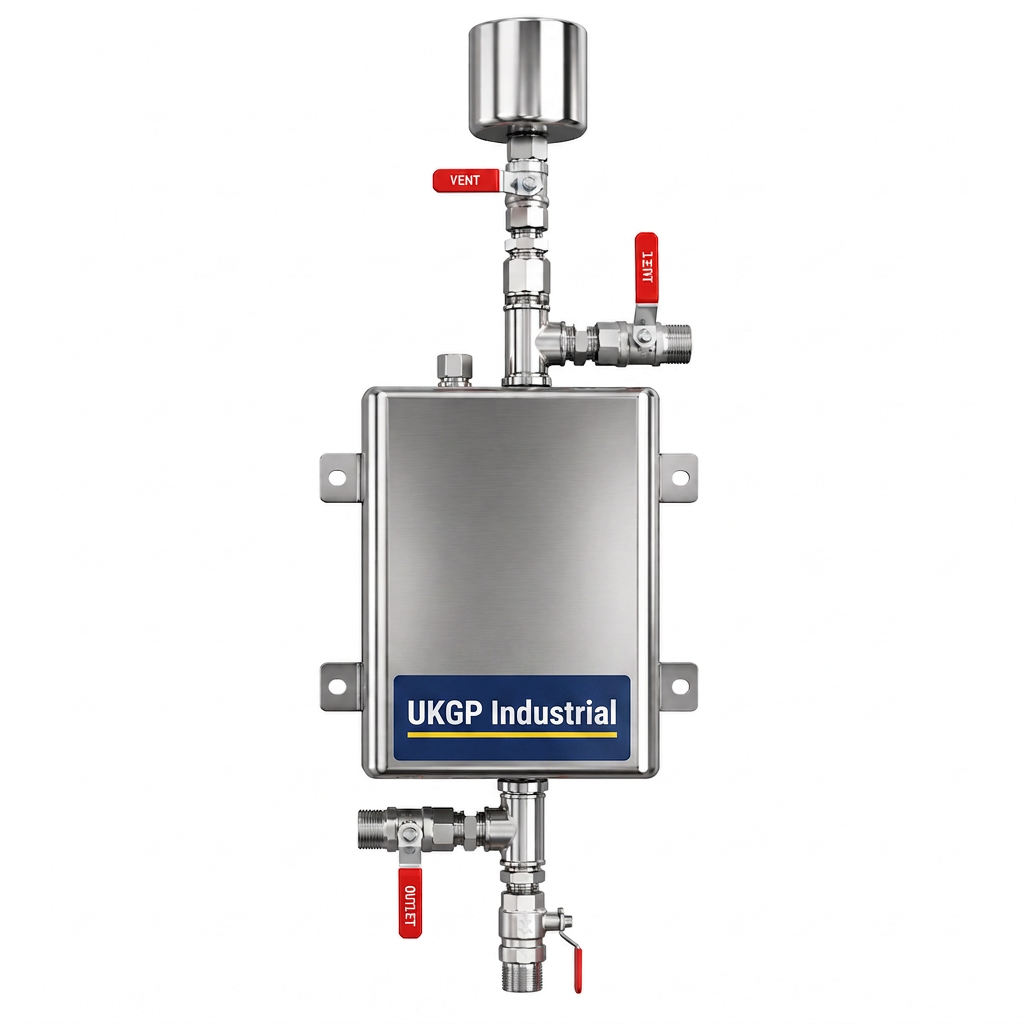
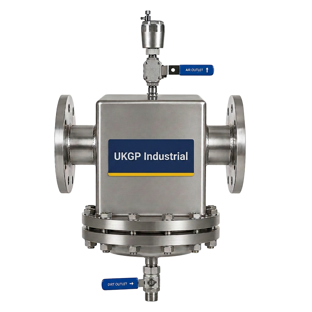
UKGP provides high-efficiency air and dirt separators that are designed to complement our heat transfer solutions. By removing both micro-bubbles and dirt particles down to 5 microns, these units ensure that the actual performance of your system mirrors the high efficiency seen on your initial plate heat exchanger diagram. Integrating these separators alongside our plate heat exchangers—which range from DN20 to DN300—creates a resilient plant-room environment. Requesting a quote for a complete package including separators and heat exchangers ensures compatibility and a streamlined procurement process for your next commercial project.
- Removal of magnetite to prevent plate channel blockage
- Elimination of micro-bubbles to reduce noise and erosion
- Compliance with BSRIA BG50 for water treatment in closed systems
- Protection of sensitive heat transfer surfaces
- Reduction in long-term maintenance costs and downtime
Maintenance and Gasket Integrity in the Diagram
For gasketed plate heat exchangers, the plate heat exchanger diagram will clearly show the perimeter and port gaskets that keep the two fluids separated. These gaskets are often clip-on or glue-on variants and are the most common point of maintenance. Over time, thermal cycling and pressure fluctuations can cause gaskets to harden or lose their elasticity. Monitoring the flow paths for external leaks or cross-contamination is a key task for FMs. A well-prepared diagram helps maintenance teams identify which specific plates or gaskets may be at fault by tracing the path of the specific fluid exhibiting the pressure loss.
The importance of the 2-year warranty offered by UKGP cannot be overstated when considering the longevity of these seals. Since our units are sized from a full thermal spec, we ensure the gasket material—be it NBR, EPDM, or Viton—is compatible with the operating temperatures and chemical additives present in your system. This proactive approach prevents the 'inter-leaking' that occurs when a gasket fails internally, potentially mixing the primary and secondary fluids. Such failures can be catastrophic in applications like domestic hot water production or process cooling where fluid purity is critical to the end-use application.
When it comes time to service a unit, the assembly diagram acts as a reference for the correct tightening dimensions of the plate pack. Over-tightening can deform the metal plates, while under-tightening leads to leaks. By following the precise measurements provided in our technical documentation, engineers can return the unit to service with confidence. We deliver these units with a 4-6 week lead time, ensuring that even if a replacement is needed during a planned shutdown, your project timelines remain intact. Our gasketed and brazed units cover a wide range of DN sizes, providing flexibility for everything from small commercial builds to large industrial complexes.
- Gasket material selection based on fluid chemistry
- Maintaining correct tightening dimensions for plate pack sealing
- Identifying signs of internal cross-contamination
- Preventative maintenance schedules for gasket replacement
- Safe opening and closing procedures for gasketed units
Material Specifications and British Standards
In the UK, plate heat exchangers must adhere to strict manufacturing standards to ensure safety and performance. When reviewing a plate heat exchanger diagram for a new project, engineers must check for compliance with the Pressure Equipment Directive (PED) and relevant BS EN standards. The choice of plate material is often determined by the chloride content of the water; for instance, standard 304 or 316 stainless steel is common, but 316L is often preferred for its superior corrosion resistance in chlorinated environments. This technical detail is a bridge between the visual diagram and the actual durability of the installed plant.
The diagram also indicates the connection types, whether threaded, flanged, or victaulic. Matching these connections to the existing pipework requires precision, especially in retrofit scenarios where space is at a premium. UKGP’s ability to size from a full thermal spec means we don’t just provide a 'standard' unit; we provide the 'correct' unit. Our range from DN20 to DN300 ensures we have the right connection size for any flow rate. This bespoke sizing reduces the need for awkward reducers or pipework modifications, saving time for M&E contractors on-site and ensuring the system operates at the design pressure indicated on the schematic.
Furthermore, thermal insulation jackets should not be overlooked. While often not shown in a basic plate heat exchanger diagram, they are essential for meeting Part L of the Building Regulations concerning energy conservation. By insulating the plate pack, you prevent radiant heat loss into the plant-room, which improves overall system efficiency and prevents the room from overheating. UKGP provides these jackets as part of our comprehensive service, ensuring your HVAC installation is not only functional but also compliant with the latest UK energy standards and sustainability targets demanded by modern building owners.
- Compliance with BS EN 14917 for expansion bellows compatibility
- Material selection for 316L vs 304 stainless steel plates
- Flange specifications from DN20 to DN300
- Adherence to Part L Building Regulations for thermal efficiency
- Meeting PED (Pressure Equipment Directive) requirements
Real-World Applications of Plate Exchanger Schematics
In practical applications, a plate heat exchanger diagram serves as the master document for integrating the unit into a wider Building Management System (BMS). By placing sensors at the four ports shown on the diagram—Inlet Primary, Outlet Primary, Inlet Secondary, and Outlet Secondary—engineers can monitor the 'approach temperature' in real-time. If the approach temperature begins to widen, it is a clear indicator of fouling within the plate pack. This data-driven approach allowed by a clear understanding of the flow paths enables predictive maintenance rather than reactive repairs, saving significant costs for facilities managers over the life of the building.
Whether you are working on a district heating scheme or a simple boiler separation circuit, the plate heat exchanger remains a critical component. The versatility of gasketed and brazed models means they can handle a vast range of pressures and temperatures. From a DN20 unit for a small commercial unit to a DN300 for a large industrial process, the principles shown in the plate heat exchanger diagram remain constant. Ensuring you have a lead time you can trust is essential; our 4-6 week delivery across the UK ensures that your project stays on track, from initial thermal sizing to final commissioning and handover.
To conclude, mastering the layout and flow paths within a plate heat exchanger diagram allows for better design, more efficient operation, and easier maintenance of UK HVAC systems. By partnering with UKGP, you gain access to expert technical support, a 2-year warranty, and products sized for your specific thermal requirements. Whether you require a gasketed unit for easy cleaning or a compact brazed unit for higher pressure applications, we provide the reliable engineering you need. Contact our Surrey-based team today to request a quote based on your thermal specification and let us help you deliver a high-performance plant-room solution.
- BMS integration for temperature monitoring
- Predictive maintenance through approach-temperature analysis
- Sizing flexibility for diverse commercial applications
- Reliable delivery within 4-6 weeks for all UK projects
- Expert technical support from a Surrey-based manufacturer
Frequently asked questions
What is the primary benefit of counter-current flow in a plate heat exchanger?
- Counter-current flow allows for a closer temperature approach between the two fluids, maximising the heat transfer efficiency and allowing the secondary fluid to be heated to a temperature very close to the primary inlet temperature.
How do I determine if I need a gasketed or brazed plate heat exchanger?
- Gasketed units are ideal for systems requiring regular cleaning or future expansion, as plates can be added or removed. Brazed units are more compact and suited for high-pressure or high-temperature applications where maintenance access to the internal plates is not required.
What is the typical lead time for a UKGP plate heat exchanger?
- Our standard lead time for both gasketed and brazed units, ranging from DN20 to DN300, is 4-6 weeks from the approval of the thermal specification.
Does UKGP provide sizing services for these units?
- Yes, we provide bespoke sizing based on your full thermal specification, including flow rates, temperatures, and allowable pressure drops, ensuring the unit is perfectly matched to your application.
What warranty is provided with your heat exchangers?
- All our plate heat exchangers come with a 2-year warranty, providing peace of mind and quality assurance for M&E contractors and consultants.