Understanding the Spirotherm Hydraulic Separator Principles
The spirotherm hydraulic separator functions primarily as a point of low pressure drop, enabling the primary boiler circuit and the secondary distribution circuits to operate independently from one another. In high-output commercial environments, where secondary pump flow rates may exceed primary boiler flow, creating a zone of zero pressure differential is critical to prevent thermal stress on the heat exchangers. By allowing these circuits to coexist without hydraulic interference, the separator ensures that the flow through the boiler remains within the manufacturer’s specified temperature differential (Delta T), typically 11K or 20K depending on the heat source. This separation is vital for maintaining the efficiency of condensing boilers and heat pumps alike, ensuring return temperatures are low enough to promote latent heat recovery.
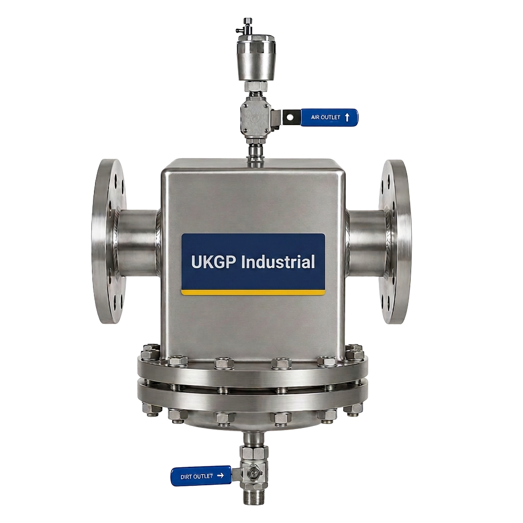
Furthermore, the internal geometry of a high-quality separator is designed to reduce fluid velocity to a point where air bubbles can rise and sediment can fall. This multi-functionality is a hallmark of modern plant room design, combining the roles of a low loss header with high-performance air and dirt removal. When consultants specify a spirotherm hydraulic separator, they are looking for a solution that simplifies the mechanical layout while providing a robust safeguard for the more sensitive components downstream. The physics of hydraulic decoupling relies on the cross-sectional area of the separator being significantly larger than the connecting pipework, effectively 'killing' the velocity and ensuring that the pump heads do not compete for flow, which could otherwise lead to premature pump failure or erratic control valve performance.
From a commercial perspective, getting the specification right at the design stage saves significant remediation costs during commissioning. UK building services engineers must account for the peak flow rates of all coupled circuits to ensure the separator is correctly sized. A common pitfall is undersizing the vessel, which leads to high internal velocities that bypass the hydraulic null point, effectively rendering the decoupling process useless. By adhering to CIBSE guidelines and UKGP engineering standards, contractors can ensure that the installed unit provides the necessary thermal buffering and separation required for complex, multi-zone commercial heating and cooling installations. Whether using threaded or flanged connections, the integrity of the hydraulic bridge remains the cornerstone of a stable HVAC system.
- Ensures total hydraulic isolation between primary and secondary circuits.
- Facilitates efficient air and micro-bubble venting at the point of highest temperature.
- Reduces flow velocity to allow for high-efficiency dirt and magnetite settlement.
- Protects heat exchangers from variable flow rates and pressure fluctuations.
Technical Specifications for the Spirotherm Hydraulic Separator
When reviewing the data sheet for a spirotherm hydraulic separator, UK engineers specifically look for the maximum flow rate capacity measured in cubic metres per hour (m3/h) and the corresponding pressure drop. In a well-designed system, the pressure drop across the separator should be negligible, often less than 1 kPa at peak design flow. This low resistance is achieved through precision internal baffles or coalescence media that disrupt the flow just enough to release air while maintaining hydraulic continuity. For large-scale UK projects, these units are typically specified with flanged PN16 connections to BS EN 1092-1 or threaded BSP connections for smaller commercial outputs between 40 kW and 150 kW, ensuring compatibility with standard plant room manifolds.
Materials of construction represent another critical specification point. While many standard units are fabricated from carbon steel with an epoxy-coated finish, the internal components responsible for air and dirt separation must be durable enough to withstand high-velocity debris and varying pH levels. In accordance with BS 8552 and BSRIA BG29, newly installed systems must undergo rigorous pre-commissioning cleaning, and having a separator with a dedicated blowdown valve allows for the easy removal of settled sludge. The integration of high-strength magnets within the separator further enhances its ability to capture magnetite, which is the leading cause of control valve sticking and heat exchanger clogging in aged UK commercial heating circuits.
A robust spirotherm hydraulic separator should also be supplied with a factory-fitted insulation jacket to minimize uncontrolled heat loss within the plant room. In the UK, CIBSE and Part L of the Building Regulations mandate high levels of thermal efficiency, and the large surface area of a hydraulic separator can be a significant source of energy waste if left uninsulated. UKGP offers a range of low loss headers and separators that come pre-fitted with bespoke EPP or mineral wool jackets, designed to meet these stringent energy requirements while allowing easy access to the air vent and drain valves for routine maintenance. Choosing a unit with a clear technical pedigree ensures that the installed system will perform reliably for its intended design life.
- Pressure ratings typically ranging from PN6 to PN16 for commercial applications.
- Available in flanged or threaded BSP configurations to suit pipework standards.
- Integrated manual or automatic air vents for continuous deaeration.
- Optional magnetic inserts to significantly improve captured magnetite rates.
Installation and Commissioning to BSRIA Standards
Correct installation of the spirotherm hydraulic separator is paramount to ensuring its long-term functionality. It should be located at the point of lowest pressure in the system, typically on the return side before the primary pumps, although placement on the flow side is often preferred for superior air removal. Contractors must ensure that there is sufficient clearance for maintenance, particularly for the removal of the magnetic rod (if fitted) and the operation of the bottom blowdown valve. Following BSRIA BG29 guidelines for pre-commissioning cleaning is essential; the separator itself can act as a collection point for debris during the flushing process, and it must be thoroughly cleaned before the system is brought into full service to prevent early-stage blockages.
During commissioning, engineers should verify the temperature differentials across the four ports of the separator. A properly sized spirotherm hydraulic separator will show a very small difference between the primary flow and secondary flow under normal load conditions. If the secondary return is significantly colder than the primary return, it indicates that the secondary flow rate is lower than the primary, which is generally acceptable. However, if the primary return is much warmer than expected, it may suggest that the primary pumps are over-pumping. Careful adjustment of variable speed pumps is necessary to balance these flows and achieve the 'hydraulic null' that the separator is designed to create, ensuring maximum efficiency for the boiler plant.
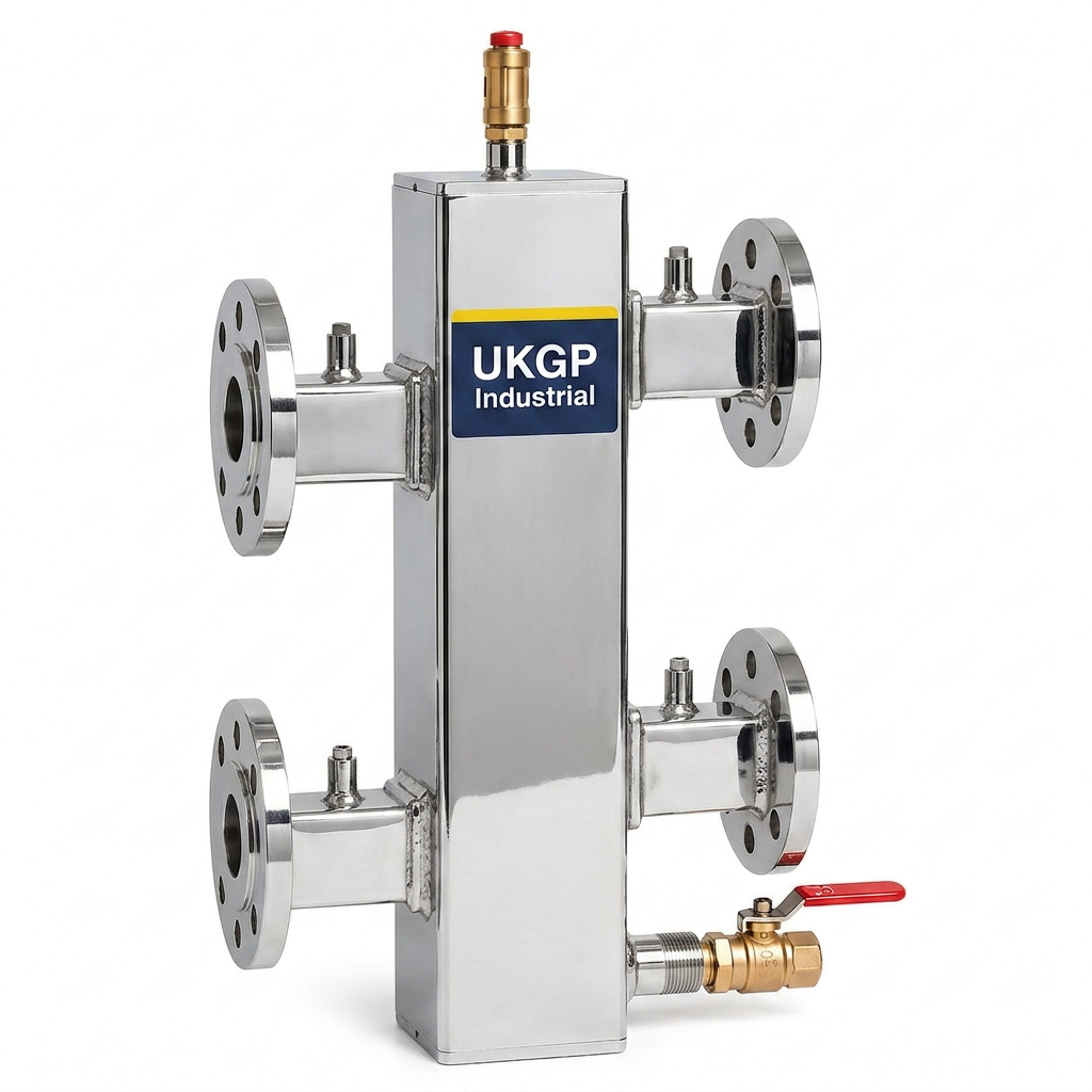
For those seeking a reliable UK-made alternative with fast lead times, UKGP low loss headers are an excellent choice for commercial projects between 40 kW and 2000 kW. These units provide the same essential hydraulic decoupling as a spirotherm hydraulic separator, available in both flanged PN16 and threaded BSP options. With a 2-year warranty and insulation jackets as standard, UKGP units are engineered to support consultants meeting BS EN 14917 and CIBSE standards. Our technical team can assist with sizing calculations to ensure your plant room achieves perfect balance. Contact us today for a quote with a 2-3 week lead time to keep your project on schedule.
- Must be installed vertically to ensure efficient air rising and dirt settlement.
- Incorporate full-bore isolation valves for ease of maintenance and blowdown.
- Verify flow directions against the manufacturer's arrow markings during fit-out.
- Ensure all air vents are piped to a safe discharge point in high-pressure systems.
Managing Water Quality with Separator Technology
Water quality management is a non-negotiable aspect of modern UK commercial HVAC maintenance, as outlined in BSRIA BG50. A spirotherm hydraulic separator plays a key role here by acting as the primary filtered bypass for the system. By slowing down the water, it allows for the mechanical separation of suspended solids that would otherwise erode silver-soldered joints or cause pitting in stainless steel heat exchangers. In high-rise developments or complex district heating schemes, the presence of such a unit is the first line of defence against the accumulation of sludge in the low-flow areas of the building, such as radiator manifolds or underfloor heating loops, which are notoriously difficult to flush once contaminated.
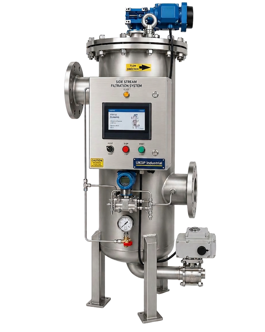
While the separator handles mechanical debris, chemical titration and monitoring remain necessary. Integrating the hydraulic separator with a side stream filtration unit or a dedicated chemical dosing pot ensures the system remains within the 8.5 to 10.5 pH range recommended for steel systems. If the water quality deviates from these parameters, the internal components of the spirotherm hydraulic separator may suffer from accelerated corrosion. Regular sampling via the separator's drain valve provides an easy way for Facilities Managers to check the clarity of the system water and the presence of any metallic particles, allowing for proactive rather than reactive maintenance strategies and extending the overall life of the plant room assets.
The commercial impact of poor water quality cannot be overstated in the UK market. Excessive air in the system leads to noise complaints from tenants and drives up pumping costs due to decreased fluid density. By utilizing a spirotherm hydraulic separator to continuously vent micro-bubbles, the system operate significantly more quietly and efficiently. Furthermore, removing air reduces the rate of internal oxidation, which is the root cause of magnetite formation. For engineers focused on long-term sustainability and reduced O&M costs, the investment in a high-grade hydraulic separator is offset by the reduction in emergency call-outs and the preservation of expensive boiler and pump warranties.
- Facilitates compliance with BSRIA BG50 water quality monitoring protocols.
- Provides a central point for system sampling and debris monitoring.
- Reduces oxidative corrosion by removing entrained air and micro-bubbles.
- Increases the efficiency of chemical inhibitors through better system circulation.
Design Considerations for Commercial Projects
When designing a commercial plant room, the space envelope is often a limiting factor. A spirotherm hydraulic separator offers a compact 'four-in-one' solution (hydraulic decoupling, air separation, dirt separation, and optional magnetite removal) that can replace several individual components. This not only saves space but also reduces the number of flanged or threaded joints, lowering the risk of leaks and reducing the total labour time during the install phase. For M&E contractors working on tight margins, the reduced 'pipe-to-pipe' dimensions of these units compared to traditional low loss headers can be the difference between a clean, professional install and a congested, difficult-to-maintain plant room.
Another design consideration is the integration of the spirotherm hydraulic separator with modern BMS (Building Management Systems). Temperature sensors (thermowells) should be installed on both the primary flow and the secondary flow ports to allow the BMS to monitor the performance of the hydraulic bridge. If the temperature differential suggests bypassing, the BMS can automatically modulate the primary pumps to match the secondary load more closely. This precision control is only possible when the hydraulic separator is sized correctly for the maximum potential flow of the system. UKGP Industrial provides detailed technical drawings and BIM objects to help consultants integrate these units into their 3D models with confidence and accuracy.
Finally, the choice between flanged and threaded connections often depends on the project's scale and the contractor's preference. Threaded BSP connections are common for smaller commercial refurbishment projects, where ease of handling is a priority. For larger new-build projects, flanged PN16 connections are standard, providing a more secure and robust seal for high-pressure systems. Regardless of the connection type, the internal functionality of the spirotherm hydraulic separator remains the same, providing the essential decoupling that protects the boiler heat exchangers and ensures the comfort of the building's occupants through stable and predictable thermal delivery throughout the heating season.
- Consult manufacturer velocity charts to avoid noise and high pressure drops.
- Use BIM objects for accurate plant room spatial planning and clash detection.
- Consider the weight of the unit when full of water for structural support planning.
- Coordinate with BMS for temperature monitoring via integrated sensor pockets.
Supply Chain and Procurement for UK M&E
In the current UK procurement climate, lead times are a significant factor for M&E contractors and procurement leads. While the spirotherm hydraulic separator is a respected specification, long waiting times for imported units can delay project handovers and inflate costs. UKGP Industrial addresses this by manufacturing our low loss headers and separators right here in the UK. We offer a 2-3 week lead time and a standard 2-year warranty on our commercial range, which covers outputs from 40 kW up to 2000 kW. Our units are available with both flanged and threaded connections, ensuring they can be dropped into existing specifications as a high-quality, technically equivalent UK-made alternative.
Quality assurance is at the heart of our manufacturing process. Every unit we supply is pressure tested and inspected to ensure it meets the rigorous standards required for UK commercial heating. By sourcing from a Surrey-based manufacturer, contractors benefit from reduced transport emissions and easier communication for bespoke requirements, such as custom port orientations or high-temperature insulation requirements. We understand the commercial pressures of the UK construction industry and aim to provide a service that is as robust as our engineering. Whether you need a single unit for a school boiler replacement or multiple flanged headers for a district heating energy centre, we can provide the technical support and rapid delivery you need.
In conclusion, whether you are installing a spirotherm hydraulic separator or a UKGP low loss header, the principles of hydraulic decoupling and system protection remain the same. These components are essential for the efficient operation of modern, high-efficiency heating systems. By focusing on correct sizing, adherence to BSRIA standards, and choosing a supplier that understands the UK market, engineers can ensure their systems run smoothly for years to come. For a competitive quote on our range of UK-manufactured low loss headers, reach out to the UKGP Industrial team today. We provide the expertise and the hardware to keep your commercial plant rooms operating at peak performance with minimal downtime.
- UK-based manufacturing reduces shipping delays and lowers the carbon footprint.
- Transparent 2-3 week lead times help maintain tight project schedules.
- Comprehensive 2-year warranty on all commercial separator and header products.
- Technical support available for sizing and specification comparison tasks.
Frequently asked questions
What is the primary function of a spirotherm hydraulic separator?
- The primary function is to decouple the primary boiler circuit from the secondary distribution circuit, ensuring that flow and pressure in one do not adversely affect the other, while simultaneously removing air and dirt from the system water.
Can I use a low loss header instead of a spirotherm hydraulic separator?
- Yes, a high-quality low loss header, such as those manufactured by UKGP, provides the same hydraulic decoupling and can be specified with integrated air and dirt separation features to match the performance of other specialized units.
What connections are available for these units?
- Commercial units are typically available with BSP threaded connections for smaller applications and PN16 flanged connections for larger systems, ensuring compatibility with standard UK commercial pipework.
Does a spirotherm hydraulic separator require an insulation jacket?
- Yes, to comply with CIBSE energy efficiency guidelines and Part L of the Building Regulations, these units should be fitted with an insulation jacket to prevent unnecessary heat loss in the plant room.
How often should the separator be serviced?
- In accordance with BSRIA BG50, the debris collection chamber should be blown down regularly, especially during the first few months of operation. Annual inspections should include checking the air vent and cleaning the magnetic insert if one is fitted.