The Fundamentals of Sizing Low Loss Header Units
In modern commercial heating, the integration of high-efficiency modular boilers often requires complex flow management. Sizing low loss header vessels correctly ensures that the primary boiler pump and the secondary distribution pumps can maintain their design flow rates without creating pressure fluctuations that lead to energy waste or equipment fatigue. British standards and CIBSE guidelines suggest that the velocity within the header should remain below 0.5 metres per second to allow for effective hydraulic decoupling and debris settlement. This low-velocity zone prevents the 'tug-of-war' between circulating pumps, which is especially critical in mixed-temperature systems featuring both underfloor heating and high-temperature radiators.
Incorrectly sizing low loss header hardware can lead to significant operational failures, including short-cycling of boilers or even pump cavitation. If the header is undersized, the velocity increases, destroying the neutral pressure point and causing the secondary circuit to pull more water than the primary can supply. Conversely, over-sizing can lead to unnecessary thermal mass and heat loss, though it is generally considered a safer failure mode than undersizing. For consultants working to BSRIA BG29 pre-commissioning cleaning standards, a correctly sized header also facilitates the capture of suspended solids, serving as a secondary point of maintenance for hydronic health in the wider system.
When approaching your next specification, consider that the thermal capacity of the system, measured in kW, dictates the flow rate required across a specific temperature differential, usually referred to as Delta T. By calculating the total flow rate in cubic metres per hour, engineers can cross-reference the required DN size against manufacturer data sheets. UKGP Industrial specializes in providing these technical nuances, offering headers ranging from 40 kW to 2000 kW to suit a vast array of commercial plant room footprints. Ensuring you have the right data at the outset prevents costly retrofits and ensures the 2-year warranty remains valid under optimal operating conditions.
- Hydraulic decoupling for primary and secondary pump circuits
- Reduction of flow velocity to below 0.5 m/s for effective separation
- Compliance with CIBSE and BSRIA BG50 maintenance guidelines
- Protection of high-efficiency modular boiler heat exchangers
The Relationship Between kW Load and DN Diameter
To begin the process of sizing low loss header vessels, you must first establish the maximum demand of the building. For instance, a 200 kW load at a 20-degree Delta T requires a significantly different flow rate than the same load at an 11-degree Delta T. Using the standard formula (kW / (Specific Heat Capacity x Delta T)), we can determine the volume of water that must pass through the header. Once this flow rate is known, selecting the DN (Nominal Diameter) becomes a matter of adhering to the 0.5 m/s velocity rule. This rule ensures that the 'neutral zone' remains truly neutral, allowing the primary and secondary fluids to mix or bypass as the load dictates.
For smaller commercial applications, such as a 50 kW to 100 kW plant room, a 2-inch or DN50 header is often sufficient, providing the necessary separation with minimal footprint. As we scale up toward 1000 kW or 2000 kW, the pipework must expand significantly, often reaching DN150 or DN200 to accommodate the massive volumetric flow. UKGP Industrial offers both threaded BSP connections for smaller units and PN16 flanged connections for larger industrial skids. These units are supplied with premium insulation jackets to minimize standing heat losses, ensuring the plant room operates at peak efficiency while meeting current Building Regulations Part L requirements.
Specifying the correct sizing low loss header installation involves looking beyond the pipe diameter alone. The height of the vessel also plays a role in the separation of air and dirt. While dedicated air and dirt separators are recommended for comprehensive system protection, a well-sized low loss header provides an initial stage of de-aeration. By selecting a header with the correct kW rating and DN size, you create a stable environment for chemicals to circulate and for sensors to provide accurate temperature readings to the Building Management System (BMS), reducing the risk of false sensor triggers caused by turbulent flow.
- DN50 for smaller 40-100 kW modular boiler banks
- DN100 to DN150 for mid-range 400-800 kW systems
- DN200 and above for large-scale 1MW+ district heating hubs
- Selection based on maximum system flow rate (m3/h)
Mitigating Air and Dirt with Proper Sizing
While the primary goal of sizing low loss header units is hydraulic separation, their secondary role in system cleanliness cannot be ignored. In accordance with BSRIA BG50, maintaining water quality is essential for the longevity of a closed-loop system. A header sized for low velocity allow heavy particles to drop to the bottom of the vessel, where they can be flushed out via a drain valve. If the header is too small, these particles remain entrained in the flow, potentially clogging heat exchangers or eroding pump impellers elsewhere in the circuit. This is why engineers often specify headers alongside high-performance filtration solutions.
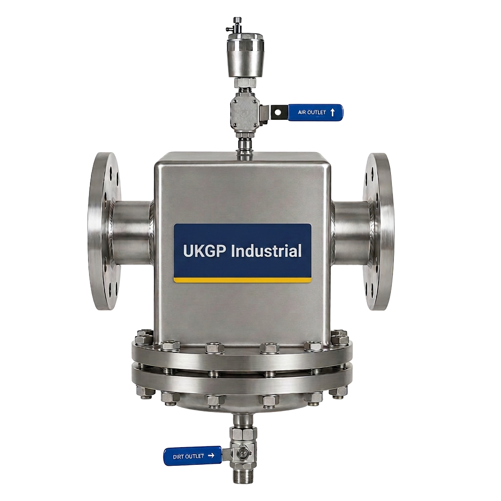
For systems where water quality is a high priority, integrating specialized equipment is the best practice. While the low loss header manages the pressure and flow, a dedicated air and dirt separator should be positioned in the main flow path to catch microbubbles and smaller magnetite particles that the header might miss. UKGP provides a range of these separators that complement our header range, ensuring that once you have handled the sizing low loss header tasks, the rest of your hydronic architecture is equally robust and protected from the internal corrosion associated with oxygen ingress and metallic debris.
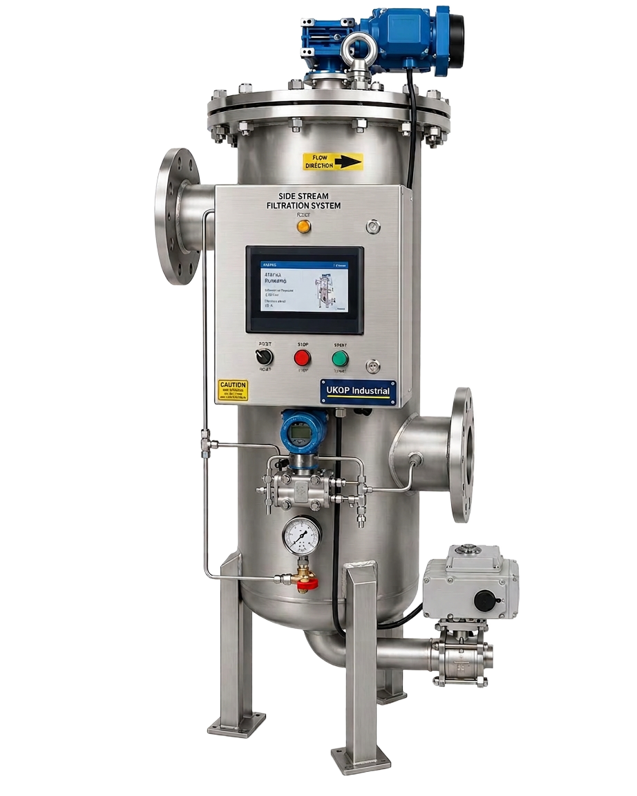
Consultants often combine the use of a low loss header with side stream filtration to meet the strict requirements of BS 8552. By ensuring the header creates a stable, low-pressure area, the side stream unit can draw a consistent flow for filtration without being affected by the varying demands of the secondary loops. This holistic approach to plant room design starts with the header as the 'anchor' of the hydraulic layout. Requesting a quote for a correctly sized UKGP header ensures that your system has the volume required to accommodate these cleaning processes without sacrificing thermal performance or increasing the pump head unnaturally.
- Integration with BSRIA BG50 water quality management strategies
- Passive de-aeration through reduced fluid velocity
- Sediment collection zone with easier maintenance access
- Stabilised flow for side stream filtration and dosing
Technical Specifications: Connections and Insulation
When you have finished sizing low loss header dimensions for your project, the next step is selecting the appropriate connection type for the site conditions. UKGP units are available in either threaded BSP for smaller, easier installations or PN16 flanged connections for higher pressure and larger volume systems. The choice often depends on the existing pipework and the ease of maintenance required. Flanged connections are typically preferred in commercial environments where the ability to easily isolate or remove the header for major plant room overhauls is a priority, whereas threaded options offer a compact solution for space-constrained plant rooms.
Thermal efficiency is just as important as hydraulic balance. Every UKGP low loss header is supplied with an insulation jacket designed to reduce the radiant heat loss into the plant room. In large 2000 kW systems, the surface area of the header is substantial; failing to insulate it can lead to overheating the plant space and a measurable drop in plant efficiency. Our jackets are removable, allowing for inspection of the vessel welds and connections as part of annual maintenance regimes. With a standard lead time of 2-3 weeks, these units can be scheduled perfectly with the mechanical installation phases of a project.
Durability is a core pillar of our manufacturing process. We understand that M&E contractors need reliable equipment that they can 'fit and forget'. Our headers come with a 2-year warranty, reflecting our confidence in the materials and welding standards used. Whether you are dealing with a 40 kW refurb or a 2000 kW new build, the principles of sizing low loss header vessels remain identical: keep the velocity low and the separation clear. This commitment to quality ensures that consultants can specify UKGP with absolute confidence that the system will perform to design specifications from commission to handover.
- BSP threaded or PN16 flanged connection options
- Includes high-grade insulation jackets as standard
- 2-3 week lead times for UK-wide site delivery
- 2-year comprehensive manufacturer warranty
Implementing Sensors and Controls
A low loss header is more than a passive vessel; it is often the primary temperature sensing point for the entire system. Sophisticated BMS strategies rely on placing temperature sensors within the header to determine if the primary circuit is meeting the demand of the secondary loops. This feedback loop is essential for modulating the boiler firing rate. If the sizing low loss header process was done incorrectly, the sensor may experience turbulent flow, leading to erratic temperature readings and inefficient boiler cycling. Ensuring laminar flow around the sensor pocket is a direct benefit of selecting the correct DN for your expected flow rates.
In many modern specifications, particularly those involving heat pumps or hybrid systems, monitoring pH levels and fluid conductivity is equally vital. UKGP offers pH sensors and transmitters that can be integrated into the system to provide real-time data on the condition of the heating water. When these sensors are placed in a system stabilized by a correctly sized header, the data is far more reliable. This allows Facility Managers to respond to chemical imbalances before they lead to corrosion or scaling, protecting the investment in the low loss header and the primary plant.
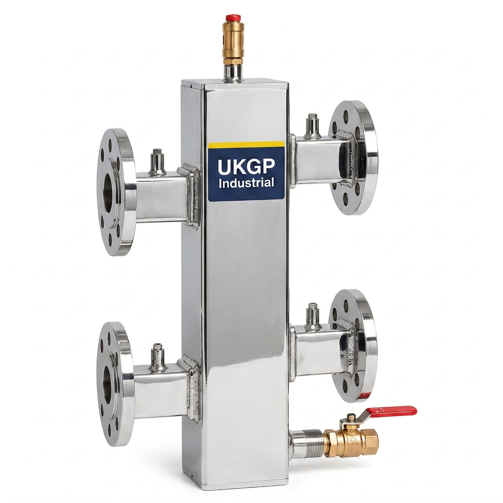
Finally, always consider the placement of the air vent and the drain valve on the header during the sizing phase. The header acts as a natural collection point for both air and sludge. Our designs incorporate specific tapping points for automatic air vents at the highest point and a 1/2 or 3/4 inch drain at the lowest point. This practical design ensures that when you choose UKGP, you are choosing a component designed by engineers for engineers. Providing clear submittals and CAD blocks, we help you finalize your sizing low loss header calculations and move your project from the drawing board to the plant room without delay.
- Tapping points for BMS temperature sensors
- Stable flow conditions for accurate pH and conductivity monitoring
- Integrated manual or automatic air vent ports
- Easily accessible drain points for sludge removal
Compliance and Hydraulic Safety Standards
Safety and compliance are non-negotiable in UK building services. Every low loss header must be designed and manufactured to withstand the maximum operating pressures and temperatures of the system, often governed by BS EN 14917 or similar pressure vessel standards where applicable. By accurately sizing low loss header units, you ensure that pressure drops across the vessel are negligible, which is a requirement for many boiler manufacturer warranties. High pressure drops within a header are a clear sign of undersizing, leading to excessive noise and increased wear on the circulating pumps.
Building services consultants must also ensure that the installation adheres to the latest version of the Water Regulations and local bylaws. Using a UKGP header ensures that you are installing a product that has been rigorously tested for the UK market. Our range, covering 40 kW to 2000 kW, is specifically tailored to meet the needs of British plant room configurations. From the moment of procurement, through the 2-3 week lead time, to final commissioning, our technical team is available to assist with any queries regarding flow calculations or DN selection to ensure your project stays on track.
In conclusion, the goal of sizing low loss header vessels is to create a reliable hydraulic break that maximizes system life and efficiency. Whether you require a compact unit for a school refurb or a large-scale flanged header for a hospital plant room, UKGP Industrial provides the technical expertise and product quality required. Our headers are not just components; they are engineered solutions backed by a 2-year warranty. Contact our Surrey-based team today to discuss your project requirements and let us help you select the perfect low loss header for your next installation.
- Manufactured to meet UK commercial thermal standards
- Protects boiler manufacturer warranties through correct flow rates
- Reduces system noise and pump wear by minimizing pressure drop
- Full technical support for consultant specifications
Frequently asked questions
What is the maximum flow velocity allowed in a low loss header?
- To ensure effective hydraulic separation and a neutral pressure zone, the velocity within the low loss header should ideally not exceed 0.5 m/s. This allows the fluid to de-aerate and for sediment to settle.
How do I convert kW to the required flow rate for sizing?
- You can calculate the flow rate using the formula: Flow Rate (m3/h) = kW / (Delta T x 1.16). Once you have the flow rate, you can select a DN size that maintains a velocity under 0.5 m/s.
What connection types are available for UKGP low loss headers?
- We provide threaded BSP connections for smaller capacities (up to approx. 120-150 kW) and PN16 flanged connections for larger commercial systems up to 2000 kW.
Do your low loss headers come with insulation?
- Yes, every UKGP low loss header is supplied with a removable insulation jacket as standard to assist with energy efficiency and compliance with Building Regulations Part L.
What is the typical lead time for a commercial header?
- Our standard lead time for low loss headers is 2 to 3 weeks, allowing for manufacturing and delivery to sites across the UK.