The Role of a Low Loss Header Schematic in Balancing Systems
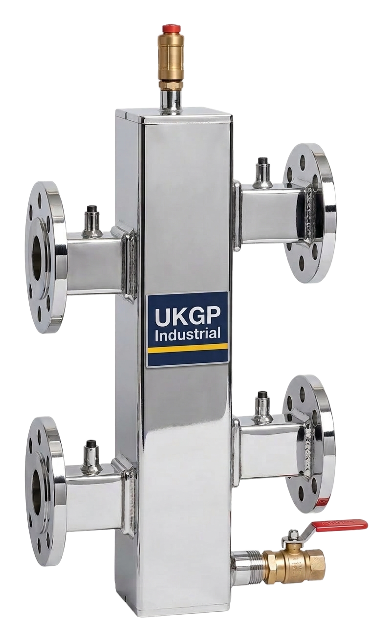
In modern commercial plant rooms, the move towards boiler cascades requires a sophisticated approach to hydraulic separation. A low loss header schematic visualises the neutral point where the primary and secondary circuits meet, allowing for independent operation of the pumps. Without a clear schematic, engineers risk installing systems where the secondary pump overcomes the primary pump, leading to ghost flows or insufficient heat transfer across the heat exchanger. This is particularly relevant when attempting to maintain the low return temperatures required for condensing boilers to operate at peak efficiency. UKGP provides the technical documentation and high-specification units necessary to turn these schematics into reliable operational realities across Surrey and the wider UK market.
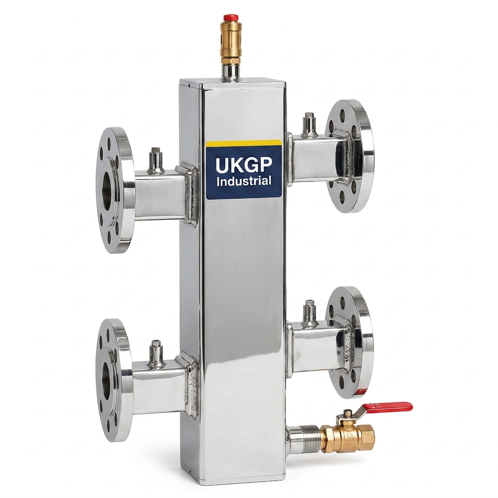
When consulting BSRIA BG50 guidelines on water treatment and system design, the importance of hydraulic stability is emphasized to prevent mechanical wear and chemical imbalances. A well-constructed schematic must account for the physical velocity of the water within the header, typically aiming for 0.1 to 0.2 metres per second. This low velocity allows for effective de-aeration and dirt settlement, which complements the primary function of pressure equalisation. By integrating a UKGP low loss header, which features a dedicated insulation jacket and robust BSP or PN16 connections, you ensure that the thermal dynamics of your schematic are preserved with minimal heat loss in the plant room environment, supporting total system longevity.
From a procurement and installation perspective, having a precise low loss header schematic simplifies the handover process between the design consultant and the M&E contractor. It reduces the likelihood of on-site errors where pipework diameters or sensor placements are misinterpreted. UKGP products are designed to fit seamlessly into these professional layouts, offering a power range of 40 kW to 2000 kW to cover everything from small commercial units to large-scale residential blocks or industrial warehouses. When you specify a UKGP unit, you are backed by a 2-year warranty and a delivery schedule that respects project timelines, with standard lead times of just 2 to 3 weeks for most commercial configurations.
- Ensures complete hydraulic decoupling between primary and secondary pumps.
- Maintains low water velocity to aid in air and dirt separation processes.
- Protect high-efficiency boilers from varying flow rates and pressure drops.
- Simplifies system commissioning by providing a neutral pressure zone.
Integrating Air and Dirt Separation into the Schematic
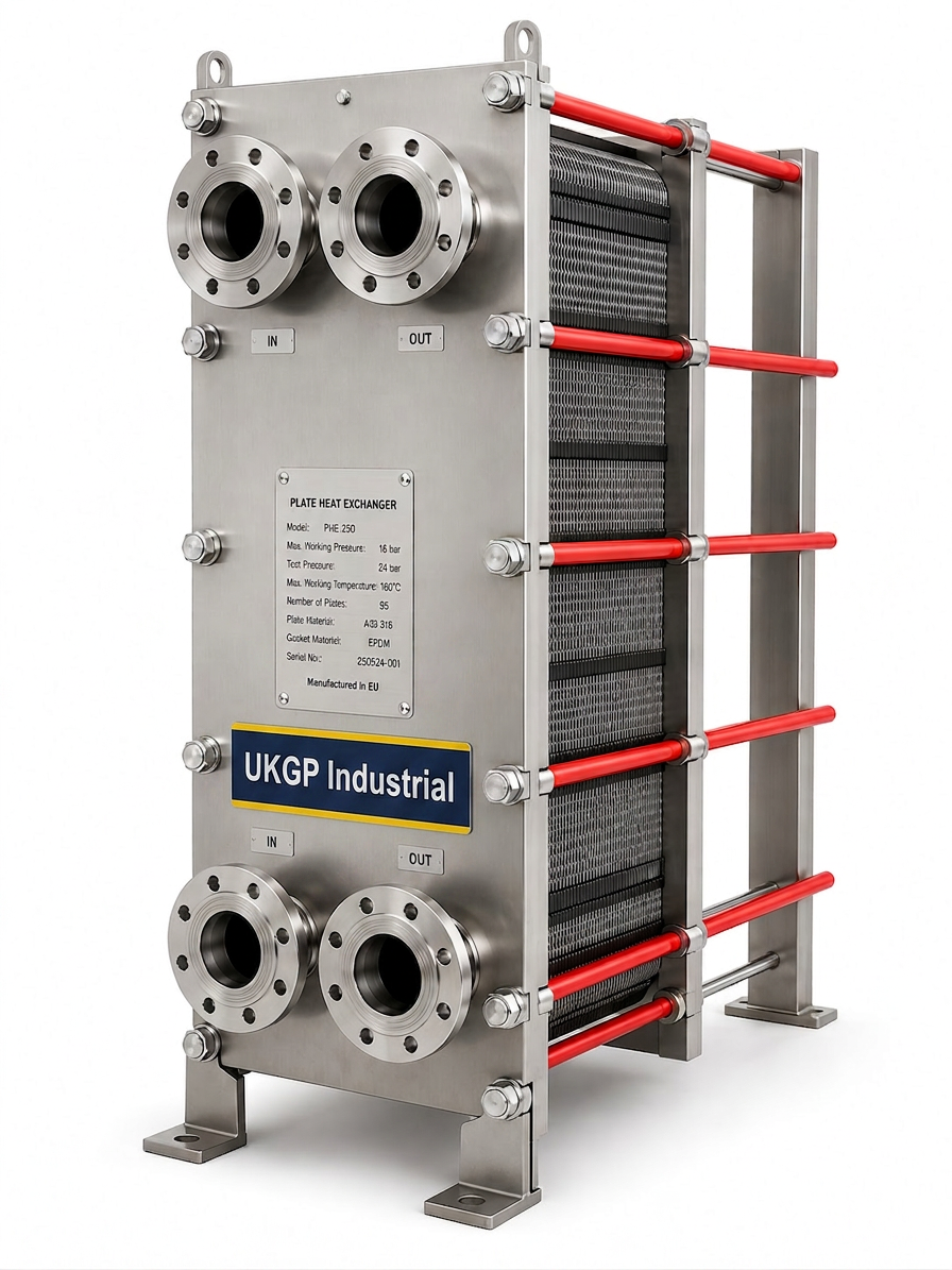
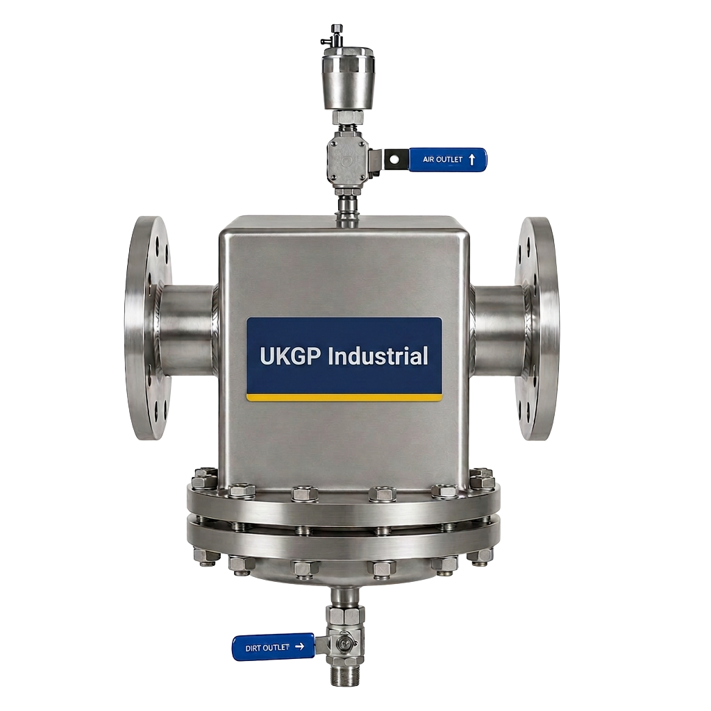
While the primary focus of a low loss header schematic is hydraulic separation, it also serves as a secondary point for debris management. In line with BSRIA BG29 pre-commissioning cleaning standards, maintaining water quality is paramount. A schematic that positions the header correctly ensures that heavier particles settle at the bottom during periods of low velocity. However, for comprehensive pipework protection, we recommend augmenting your design with dedicated separators. A UKGP air and dirt separator works in tandem with the header to capture micro-bubbles and magnetite that the header alone might miss. This dual-layered approach is the gold standard for UK facility managers looking to reduce long-term maintenance costs and prevent the fouling of plate heat exchangers or control valves.
The schematic should clearly indicate the flow direction and the entry points for automatic air vents at the highest point of the header. Many seasoned engineers prefer to see the low loss header schematic include a drain valve at the base for easy flushing of collected sludge. By specifying UKGP components, you are choosing UK-manufactured quality that adheres to rigorous British standards. Our separators and headers are built to withstand the demands of high-pressure commercial systems, ensuring that your cascade remains free from the erosive effects of trapped air and the efficiency-draining impact of system debris. This proactive design philosophy is what separates a standard installation from a high-performance HVAC solution.
Consider the commercial implications of system failure due to poor water quality or air locks. A school, hospital, or office block cannot afford downtime caused by a poorly balanced cascade. By following a structured low loss header schematic and integrating UKGP's robust hardware, you mitigate the risk of pump cavitation and sensor errors. Our technical team can assist in reviewing your requirements to ensure the chosen units match the flow rates dictated by your schematic. With a focus on reliability and commercial awareness, UKGP provides the components that make complex hydraulic designs work in the real world, ensuring your project meets all CIBSE and BSRIA recommendations for modern heating networks.
- Position air vents at the top of the header for continuous de-aeration.
- Use a bottom drain valve on the header for simplified maintenance flushing.
- Combine headers with dedicated air and dirt separators for maximum protection.
- Ensure flow velocities remain within BSRIA recommended limits to prevent noise.
Technical Specifications for Low Loss Header Selection
Selecting the correct unit for your low loss header schematic requires a deep dive into the peak flow rates and temperature differentials of the system. A common mistake is undersizing the header, which increases water velocity and defeats the purpose of the neutral zone. UKGP headers are available in sizes catering from 40 kW up to 2000 kW, ensuring that whether you are installing a twin-boiler cascade or a massive industrial bank, there is a technical fit. These units come with either flanged PN16 or threaded BSP connections, providing the flexibility needed for both new builds and plant room refurbishments. The inclusion of an insulation jacket as standard ensures compliance with domestic and commercial energy saving regulations by minimising standing heat losses.
In any professional low loss header schematic, the placement of temperature sensors is vital for the Building Management System (BMS) to accurately modulate the boiler cascade. UKGP headers include well-positioned sensor pockets to ensure the feedback loop is precise. This precision prevents the common issue of 'short-cycling,' where boilers fire and extinguish rapidly because the flow and return temperatures are not being correctly monitored within the header. When you source your header from UKGP, you are getting more than just a steel vessel; you are getting a precision-engineered component with a 2-year warranty that has been pressure tested to ensure it meets the highest safety and performance standards in the UK market.
Procurement leads and M&E contractors often face tight deadlines, which is why UKGP prioritises a 2-3 week lead time. We understand that on-site delays are costly and that having the right equipment arrive exactly when the pipework is being hung is essential. Our headers are designed for ease of installation, with sturdy mounting points and clear labelling that mirrors your low loss header schematic. By choosing a UK-based supplier, you also benefit from easier logistics and a technical support desk that understands the specific nuances of UK building regulations and CIBSE guidelines. Contact our Surrey office today to receive a competitive quote and technical data sheets for your next commercial heating project.
- Available for power outputs from 40 kW through to 2000 kW.
- Connection options include threaded BSP or flanged PN16 to suit all specs.
- Supplied with a high-quality insulation jacket to reduce thermal bypass.
- Fast UK lead times of 2-3 weeks to keep your site schedule on track.
Primary vs Secondary Flow in the Schematic Design
The core logic of a low loss header schematic is managing the three possible flow conditions: primary flow equal to, greater than, or less than secondary flow. In a heating-led cascade, the goal is often to have a slightly higher primary flow rate to ensure the secondary circuit always has access to the required temperature. However, during low-demand periods, the pumps must be able to back off without causing hydraulic interference. The schematic must show how the header acts as a bypass in these scenarios. UKGP units are engineered to handle these shifts in fluid dynamics flawlessly, providing a buffer that protects expensive boiler heat exchangers from thermal shock and unexpected pressure spikes.
A well-documented low loss header schematic also aids in the commissioning process, as it allows the balancing engineer to set the pump speeds correctly. By observing the temperature differential across the header, they can confirm if the hydraulic separation is functioning as intended. If the schematic is ignored and the header is bypassed, the system will likely suffer from uneven heat distribution, with the furthest radiators or AHUs failing to reach design temperature. UKGP's range of headers is designed to prevent these issues by providing a generous internal volume that absorbs the turbulence of colliding flow paths, leading to a much smoother and more predictable system performance across the entire building footprint.
For consultants designing high-value commercial properties, the reliability of the schematic translates directly into client satisfaction. A building that heats up quickly and operates quietly is a testament to good hydraulic design. UKGP supports this by offering products that are not only functional but also built to last. Our headers are fabricated from heavy-duty carbon steel and finished to professional standards, ensuring they remain a cornerstone of the plant room for decades. When you align your low loss header schematic with UKGP hardware, you are investing in a system that meets the rigorous demands of BS EN 12828 and other relevant UK standards for heating system design in buildings.
- Accommodates primary flow rates exceeding secondary demand during heat-up.
- Facilitates a bypass function during low-load periods to protect boilers.
- Reduces pump head requirements by creating a low-resistance path.
- Essential for multi-zone systems with varying temperature requirements.
Best Practices for Mechanical Installation
Once the low loss header schematic is finalised, the physical installation must mirror the design to avoid air pockets and stagnant zones. It is essential that the header is mounted vertically to allow for the natural buoyancy of air to reach the top and for dirt to settle at the bottom. The schematic should show clear pipework runs with minimal bends immediately entering and exiting the header to ensure laminar flow where possible. UKGP headers are designed with clear orientation markings to assist site teams. Furthermore, given the weight of larger 2000 kW units, the structural supports must be accounted for in the initial plant room layout, a detail often overlooked until the equipment arrives on site.
Thermal insulation is another critical factor that must be reflected in your low loss header schematic and subsequent installation. Without the insulation jacket provided by UKGP, the header acts as a giant radiator in the plant room, wasting energy and potentially skewing the readings of the BMS sensors. Our jackets are designed for a snug fit, ensuring that every kilowatt produced by the boiler cascade is directed toward the secondary load rather than heating the plant room air. This attention to detail reflects our commitment to assisting UK businesses in meeting their energy efficiency targets and reducing carbon footprints in line with government mandates and industry best practices.
Finally, ensure that all connections—whether they are PN16 flanges or BSP threads—are checked against the schematic before the system is filled and chemically treated according to BS 8552. UKGP provides comprehensive documentation with every unit to ensure that the installer knows exactly how to integrate the header into the wider system. With our 2-year warranty, you can have confidence that the hardware will perform as expected, provided the low loss header schematic has been followed. For any bespoke requirements or technical queries regarding flow rates and sizing, our expert team in Surrey is available to provide the necessary guidance to ensure your project’s success.
- Always mount the header vertically as per the design schematic.
- Ensure the insulation jacket is correctly fitted to prevent energy loss.
- Verify all sensor pockets are accessible for future maintenance and calibration.
- Double-check flange alignments to prevent stress on the header nozzles.
Ensuring Long-Term Performance of the Cascade
A low loss header schematic is not just a 'set and forget' document; it is a reference piece for the entire lifecycle of the HVAC system. As building loads change—perhaps due to an extension or a change in usage—the schematic should be updated to ensure the header is still appropriately sized. UKGP’s versatile range makes it easy to upgrade components if a system's capacity increases from, say, 500 kW to 1000 kW. By maintaining a clear schematic, facility managers can easily troubleshoot issues such as temperature drop-offs or pump inefficiencies, knowing exactly how the hydraulic circuits are intended to interact within the plant room environment.
Regular maintenance, as outlined in CIBSE Guide M, should include checking the integrity of the header and its associated components. This includes cleaning the internal magnets (if fitted) and ensures that the air vents are not blocked. Because UKGP headers are built with high-quality materials, they are resistant to the common pitfalls of internal corrosion, especially when used in conjunction with a correct chemical dosing regime via a UKGP dosing pot. The clarity provided by a professional low loss header schematic ensures that any technician, even one new to the site, can quickly grasp the system's logic and perform the necessary checks to keep the cascade running at peak performance for years to come.
To conclude, the success of a commercial boiler cascade hinges on the precision of the low loss header schematic and the quality of the hardware used to implement it. UKGP Industrial is proud to be a leading UK supplier of these essential components, offering the technical expertise and reliability that M&E professionals demand. Whether you need a small 40 kW threaded unit or a large 2000 kW flanged header, we have the solution ready for dispatch within 2-3 weeks. Reach out today for a consultation or a quote, and let us help you optimise your next plant room design with our industry-leading low loss headers and bespoke HVAC accessories.
- Update the schematic whenever secondary circuits are modified or added.
- Conduct annual inspections of the header's insulation and sensor accuracy.
- Integrate the schematic into the building's O&M manual for future FMs.
- Trust UKGP for replacement parts and technical upgrades as systems evolve.
Frequently asked questions
What is the primary purpose of a low loss header schematic?
- A low loss header schematic is used to design the hydraulic separation between a primary heat source, like a boiler cascade, and secondary distribution circuits. It ensures that the pumps in each circuit can operate independently without interfering with one another's flow rates.
What flow velocity should be maintained in a low loss header?
- To ensure effective separation and to allow for air and dirt removal, the water velocity within the low loss header should typically be maintained between 0.1 and 0.2 metres per second.
Can UKGP provide headers for large industrial cascades?
- Yes, UKGP supplies low loss headers for commercial and industrial applications ranging from 40 kW up to 2000 kW, with options for PN16 flanged or BSP threaded connections.
Are insulation jackets included with UKGP low loss headers?
- Yes, all UKGP low loss headers come with a high-quality insulation jacket to minimise heat loss and improve overall system efficiency, which is a key requirement for modern UK building regulations.
What is the typical lead time for a UKGP header?
- We typically offer a lead time of 2-3 weeks for our standard commercial low loss headers, ensuring that your project stays on schedule.