The Engineering Logic of a Low Loss Header Piping Diagram
In modern commercial HVAC design, the low loss header piping diagram serves as the foundational blueprint for ensuring hydraulic independence. The primary function of this configuration is to create a zone of neutral pressure, allowing the primary circuit pumps and secondary circuit pumps to operate autonomously without influencing each other's flow rates. This is particularly critical in systems using high-efficiency condensing boilers or air-source heat pumps, where maintaining a specific temperature differential (Delta T) is vital for operational efficiency and equipment longevity. A well-constructed diagram will clearly illustrate the point of zero pressure drop, which prevents the pumps from 'fighting' one another, a common cause of premature mechanical failure and high energy consumption in poorly designed systems.
When consulting a low loss header piping diagram, engineers must focus on the physical velocity of the fluid within the header itself. To achieve effective hydraulic separation, the vertical velocity within the vessel should generally not exceed 0.1 to 0.2 metres per second. This low-velocity environment allows the primary and secondary flows to mix slightly while maintaining distinct pressure regimes. Failure to account for these velocities in your initial design can lead to ghost flows, where water circulates through circuits that are technically turned off, or inadequate heat transfer during peak demand. This is why UKGP Industrial provides comprehensive technical support for our LLH range, ensuring that your theoretical schematic translates perfectly into a high-performance physical installation with minimal onsite complications.
From a commercial perspective, getting the layout right at the design stage reduces the need for expensive post-installation rectification. A standard low loss header piping diagram will include essential components such as air vents at the highest point and a drain valve at the lowest point to manage debris and non-condensable gases. By adhering to CIBSE guidelines and UK building regulations, designers can specify a system that balances thermal loads effectively. Our UKGP low loss headers are engineered to facilitate these precise layouts, supporting outputs from 40 kW to 2000 kW. With threaded BSP or flanged PN16 connections available, our units integrate seamlessly into any professional piping schematic, providing the reliability required for large-scale Surrey-based or national commercial developments.
- Allows for hydraulic separation between primary and secondary circuits.
- Maintains constant flow through the boiler to prevent overheating or cycling.
- Facilitates the removal of air and dirt through low-velocity settling.
- Ensures return temperatures are optimised for condensing efficiency.
Correct Pump Positions in the Secondary Circuit
Pump positioning is perhaps the most critical variable in any low loss header piping diagram. To ensure the system operates under positive pressure and to avoid cavitation, the secondary pumps should be situated on the flow (supply) pipework, pulling water from the header and pushing it toward the heat emitters. This orientation ensures that the pump is and remains the highest pressure point in the distribution loop. When pumps are incorrectly placed on the return leg without consideration for the neutral point, it can lead to negative pressure zones, which effectively suck air into the system through automatic air vents or micro-leaks, leading to accelerated corrosion and reduced heat transfer efficiency across the building's zones.
Furthermore, the relationship between the primary pump (often integrated within the boiler) and the secondary pumps must be managed via the header's common port. The low loss header piping diagram must illustrate the primary pump circulating water through the heat source and back to the header at a constant rate, while the secondary pumps vary their speed via VSDs (Variable Speed Drives) based on building demand. If the secondary pump flow exceeds the primary flow, the header will draw return water into the supply mix, lowering the flow temperature. Conversely, if primary flow exceeds secondary, the supply temperature remains high but the return temperature to the boiler rises. Precision in pump head calculations and positioning is therefore non-negotiable for system stability.
Engineers should also consider the use of check valves or non-return valves in the pump sets as indicated on the low loss header piping diagram. These prevent backflow when certain zones are inactive, which is essential in multi-zone commercial buildings like offices or hospitals. UKGP Industrial’s low loss headers, which come with a 2-year warranty and a standard 2-3 week lead time, are designed with these pump dynamics in mind. Our units feature a pre-fitted insulation jacket to prevent heat loss at the neutral point, ensuring that the thermal energy your pumps are moving is delivered exactly where it is needed without parasitic losses common in uninsulated bespoke fabrications.
- Secondary pumps should be installed on the flow side for positive pressure.
- Primary pump flow must be matched to the boiler manufacturer's minimum requirements.
- Variable speed drives should modulate based on differential pressure sensors.
- Ensure non-return valves are positioned to prevent cross-circuit flow.
Integrating Air and Dirt Separation Mechanisms
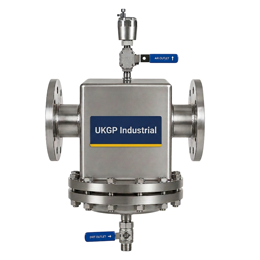
While a low loss header provides some natural separation due to its low-velocity zone, high-specification systems often require dedicated components to meet BSRIA BG29 and BG50 standards for water quality. A comprehensive low loss header piping diagram will often show a standalone air and dirt separator positioned upstream of the header on the primary return or flow. This proactive approach to water treatment protects the narrow waterways of modern heat exchangers from magnetite and sludge. Even with the internal baffles found in some headers, the sheer volume of debris in older systems being retrofitted with new boilers necessitates secondary filtration to maintain high efficiency and prevent pump impellers from clogging.
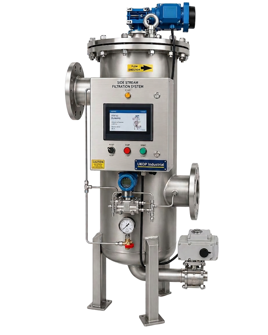
The inclusion of these components in your low loss header piping diagram ensures that the total system volume is treated, not just a portion. For larger commercial projects, we recommend the addition of a side-stream filtration skid to complement the header. This prevents the buildup of suspended solids which can otherwise settle in the low-flow area of the header itself. If a header becomes a debris trap, it can restrict flow and cause a pressure drop where none should exist, effectively defeating the purpose of hydraulic separation. By specifying a UKGP air and dirt separator alongside your header, you create a comprehensive protection strategy that satisfies the stringent requirements of M&E contractors and facilities managers alike.
Proper maintenance access for these separators must be noted on the layout. If the low loss header piping diagram places these units in inaccessible voids, the periodic flushing required for dirt removal will be neglected. This leads to increased pressure drops and reduced thermal performance. UKGP Industrial provides flanged PN16 and threaded BSP options for all separation equipment, allowing for easy integration into standard plant-room footprints. When you request a quote for our low loss headers (40-2000 kW), consider the complete hydraulic package to ensure the longevity of the entire plant, backed by our technical expertise and commitment to fast UK delivery.
- Position air separators at the highest temperature point for maximum efficiency.
- Place dirt separators on the main return to protect boilers.
- Ensure the low loss header piping diagram includes clear bypass and drain lines.
- Maintain water quality to BSRIA BG50 standards to protect the 2-year warranty.
Sizing and Connection Requirements for Commercial Headers
Selecting the correct size for a low loss header is as important as the low loss header piping diagram itself. The vessel must be sized based on the maximum possible flow rate of whichever side (primary or secondary) is higher. If the header is undersized, the fluid velocity will be too high, preventing hydraulic separation and turning the header into a simple junction box with significant pressure loss. Most engineers use the '4D' or '3D' rule for sizing the diameter of the vessel relative to the pipework diameter, but modern computational methods or manufacturer-provided selection charts are more reliable for ensuring the 0.1 m/s velocity target is met for the given kW output.
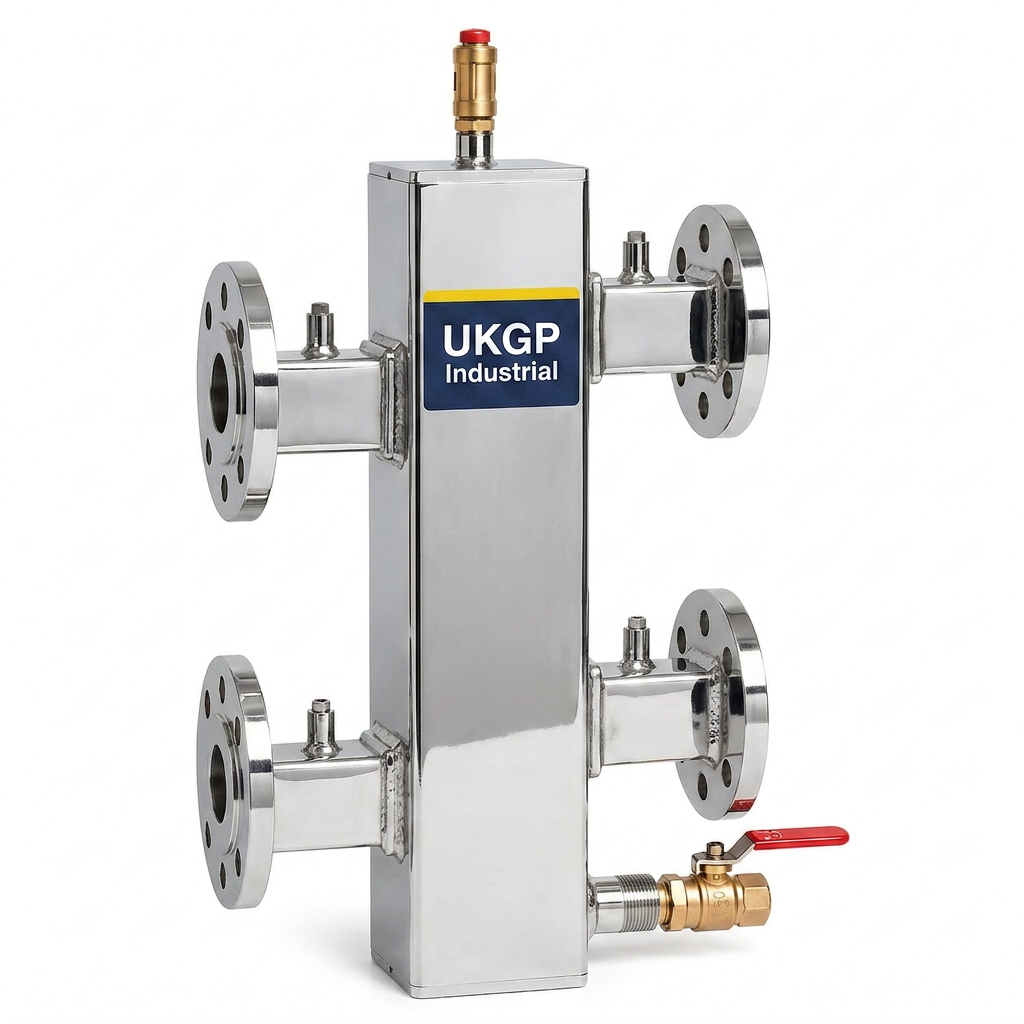
UKGP Industrial offers a range of headers spanning from 40 kW up to 2000 kW, catering to everything from light commercial units to large industrial district heating centres. The low loss header piping diagram should specify whether threaded BSP connections are sufficient for smaller loads (typically below 100 kW) or if PN16 flanged connections are required for larger bore pipework. Our units are manufactured to the highest standards, ensuring that the heavy-duty flanged or threaded ports can withstand the mechanical stresses of a commercial plant room. Each header also features a high-grade insulation jacket, which is essential for meeting SAP and SBEM energy calculations in modern UK building projects.
In addition to the main ports, the diagram must account for sensor pockets. A temperature sensor located in the top of the header is often used to provide feedback to the boiler's BMS (Building Management System), allowing the heat source to modulate based on the actual temperature being delivered to the secondary circuits. UKGP headers come with dedicated 1/2" or 3/4" sockets for these sensors as standard. This level of detail in our manufacturing helps consultants and contractors deliver a project that is not only hydraulically sound but also intelligent and responsive to the building's fluctuating thermal demands, all within a competitive 2-3 week lead time.
- Size based on maximum flow rate (m3/h) rather than just kW load.
- Specify flanged PN16 connections for robust commercial installations.
- Check that sensor pockets are included for BMS integration.
- Confirm that insulation jackets are included to meet Part L requirements.
Operational Benefits of the Low Loss Header Piping Diagram
The long-term operational benefits of following a precision low loss header piping diagram cannot be overstated. By ensuring the primary and secondary circuits remain hydraulically separate, the boilers are protected from thermal shock. Thermal shock occurs when cold return water from the secondary circuit enters a hot boiler heat exchanger too quickly, leading to stress fractures and leaks. The mixing action within the low loss header tempers this return water, effectively pre-heating it before it returns to the boilers. This is a primary requirement for many manufacturer warranties on commercial condensing boilers and heat pumps, making the LLH a critical insurance policy for the plant room.
Furthermore, an accurate low loss header piping diagram facilitates easier commissioning and balancing. Without a header, trying to balance multiple variable speed pumps in a complex building is a logistical nightmare, as a change in one zone ripple through the entire system. With the header acting as a hydraulic break, each secondary zone can be balanced independently of the primary circuit. This significantly reduces the time required by commissioning engineers on-site and ensures that the building handover process is smooth and consistent with BSRIA guidelines. It also allows for easier future-proofing, as additional zones can be added to the secondary side without redesigning the primary boiler loop.
Energy efficiency is the final, and perhaps most important, benefit. By allowing the primary pumps to operate at their minimum required flow and the secondary pumps to modulate down to meet low demand, the total electrical consumption of the pump estate is minimised. This is reflected in lower operational costs for the facility manager and a reduced carbon footprint for the building owner. When you source a UKGP low loss header, you are investing in a product designed to facilitate these efficiencies. Our 2-year warranty provides peace of mind that the vessel will perform reliably, while our local UK manufacturing ensures that technical queries regarding your piping diagram are handled by experts who understand UK standards.
- Protects heat exchangers from damaging thermal shock.
- Simplifies the balancing and commissioning of complex M&E systems.
- Facilitates easier expansion or modular upgrades to the plant room.
- Reduces parasitic pumping energy through effective decoupling.
Common Pitfalls to Avoid in Header Installation
Even with a clear low loss header piping diagram, certain installation errors can undermine system performance. One common mistake is the 'short-circuiting' of the header, where the distance between the primary and secondary connections is too small. This prevents adequate mixing and separation, leading to turbulent flow and potential air entrainment. Designers must ensure that the header height is sufficient to allow for the gravitational settling of dirt and the rising of air bubbles. UKGP Industrial headers are designed with optimised internal dimensions to prevent these issues, ensuring that the physical vessel exceeds the minimum requirements of standard 'short' headers often found in the market.
Another pitfall is neglecting the placement of air vents and dosing pots. A low loss header piping diagram remains incomplete without showing how water treatment chemicals will be introduced. It is standard practice to install a dosing pot on the secondary return, allowing for the introduction of corrosion inhibitors to protect the entire system. Without proper chemical treatment as per BS 14917 or BS 8552, even the best-designed header will eventually suffer from internal corrosion. Integrating a UKGP dosing pot ensures that your maintenance regime is as robust as your hydraulic design, protecting your investment for the 25+ year lifespan expected of high-end commercial HVAC installations.
Finally, ensure that the insulation jacket is fitted correctly and that all unused ports are properly plugged and pressure tested. Heat loss from an uninsulated 1000 kW low loss header can be significant, especially in high-temperature systems. At UKGP Industrial, we provide the insulation jacket as part of the standard package to ensure your project complies with energy efficiency targets from day one. If you are currently working on a plant-room layout, contact us for specifications or a quote. Our 2-3 week lead time ensures that your project remains on schedule, while our engineering team can review your requirements to ensure the chosen header meets the exacting needs of your specific application.
- Avoid 'short' headers that provide insufficient separation distance.
- Ensure all unused sockets are capped and verified during pressure tests.
- Always install a dosing pot to maintain chemical concentration levels.
- Verify that the insulation jacket is fitted tightly to prevent thermal bypass.
Frequently asked questions
What is the primary purpose of a low loss header piping diagram?
- The primary purpose is to illustrate the hydraulic separation between the primary heat source circuit and the secondary distribution circuits, ensuring constant flow for the boilers and variable flow for the building demand.
Where should the pumps be placed in the diagram?
- The primary pump is typically on the boiler return or flow to maintain constant circulation through the heat source. Secondary distribution pumps should be placed on the flow side of the header to push water into the building circuits.
What velocity should be maintained inside the header?
- To ensure effective hydraulic separation and air/dirt removal, the vertical velocity within the low loss header should be kept between 0.1 m/s and 0.2 m/s.
Can a low loss header handle multiple heat sources?
- Yes, a low loss header is often used to combine flows from multiple boilers or solar/heat pump inputs before distributing them to various heating zones.
What are the common connection types for UKGP headers?
- We offer threaded BSP connections for smaller units and PN16 flanged connections for larger commercial headers, covering requirements from 40 kW to 2000 kW.