The fundamental principles of low loss header installation
A successful low loss header installation serves as the hydraulic heart of a commercial heating system, ensuring that the primary boiler circuit and the secondary distribution circuits operate independently. Without this separation, variable speed pumps on the secondary side can interfere with the fixed or minimum flow requirements of the primary heat source, potentially leading to boiler cycling or premature component failure. Engineers must consider the volumetric flow rates of both circuits to ensure the header acts as a true neutral point of pressure, facilitating efficient heat transfer without turbulence.
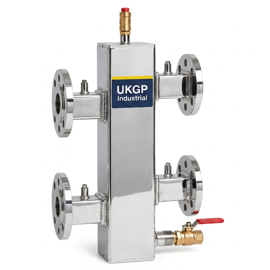
When planning your low loss header installation, the 'four-port' rule is the industry standard, where the primary flow and return and secondary flow and return are piped into a vertical or horizontal vessel. This vessel must be sized with a low internal velocity—typically not exceeding 0.5 metres per second—to allow for gravitational separation of air and dirt. UKGP Industrial provides commercial units covering 40kW to 2000kW, ensuring that even large-scale district heating or multi-storey commercial developments maintain hydraulic equilibrium through precision-engineered vessel geometry.
Failure to adhere to best practices during the initial installation phase often results in poor temperature stratification and inefficient condensing. By choosing a UKGP low loss header, contractors benefit from a unit supplied with an insulation jacket as standard, reducing standing heat losses in line with Part L of the Building Regulations. Whether you require a threaded BSP connection for smaller plant rooms or PN16 flanged connections for high-output industrial applications, the physical mounting and orientation of the header remain critical for long-term operational stability and ease of maintenance.
- Ensure primary and secondary circuits are hydraulically decoupled.
- Maintain low internal velocity (approx 0.5m/s) to prevent turbulence.
- Utilise a 4-port configuration for maximum flow bypass flexibility.
- Position the header to allow for air venting at the highest point.
Correct pipework orientation and sizing requirements
Designers must pay close attention to the pipework diameter leading to and from the vessel during a low loss header installation. It is common practice to size the header itself significantly larger than the connecting pipework to achieve the required velocity reduction. If the connecting pipes are undersized, the kinetic energy of the incoming water can cause mixing within the header, effectively bypassing the secondary circuit and returning high-temperature water directly to the boiler, which prevents condensing and reduces SAP ratings. Proper pipe sizing ensures that the pressure drop across the header is negligible.
The proximity of the pumps to the header is another vital consideration for M&E contractors. Ideally, primary pumps should be located on the return leg to the boiler, pushing water into the heat exchanger, while secondary pumps draw from the flow side of the header. This configuration ensures that the header remains the point of lowest pressure in the system, preventing air ingress issues that commonly plague commercial circuits. Following BSRIA BG29/2021 pre-commissioning cleaning guidelines is also essential during the pipework phase to remove mill scale and debris before the system becomes operational.
In constrained plant room environments, horizontal low loss header installation is possible, though vertical orientation is generally preferred for its natural de-aeration properties. If your project involves complex multi-zone distribution, such as underfloor heating combined with high-temperature radiators, the pipework must be balanced meticulously. UKGP units are designed for such versatility, offering a 2-year warranty and a typical 2-3 week lead time, allowing project managers to stick to tight construction schedules without compromising on the quality of the mechanical envelope or the integrity of the hydraulic separation.
- Size header diameter based on total combined flow rate of all circuits.
- Maintain adequate straight pipe runs before entering the header.
- Use high-quality PN16 or BSP fittings to match existing plant specifications.
- Install isolation valves on all four ports to facilitate future maintenance.
Integrating air and dirt separation in the circuit
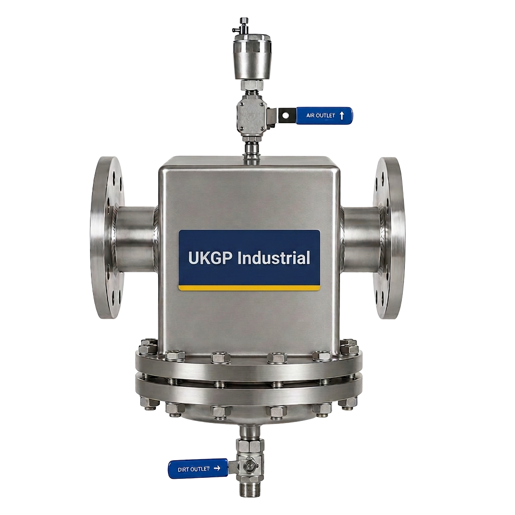
While a low loss header provides a degree of natural separation, it should ideally be supported by dedicated air and dirt separators to meet BSRIA BG50 water quality standards. During a low loss header installation, integrating a magnetic separator on the secondary return protects the boiler's internal components from magnetite buildup. Magnetite is the leading cause of pump failure and heat exchanger blockages in UK commercial systems. By stripping these contaminants before they arrive at the header, you ensure that the neutral pressure zone remains clean and free of sludge that could impair flow.
Air management is equally critical; an automatic air vent should be fitted to the top of the header to bleed off micro-bubbles released as the water temperature rises. In systems where the low loss header is the highest point of the primary circuit, it acts as an effective de-aerator. However, in high-rise buildings, additional de-aeration equipment may be required. Effectively managing both air and dirt prolongs the life of the secondary pumps and ensures that the low loss header installation remains an asset rather than a point of accumulation for system debris.
If you are retrofitting a plant room with modern condensing boilers, the combination of a UKGP low loss header and an integrated separator is a robust solution. The inclusion of a drain valve at the bottom of the header allows for the flushing of any settled solids during annual service visits. This proactive approach to system health reduces the frequency of emergency call-outs and ensures that the facility manager can maintain the building's thermal comfort levels without interruption. Requesting a quote for a combined separator and header package can often streamline procurement and ensure technical compatibility.
- Install magnetic separators to capture iron oxide and slag.
- Utilise automatic air vents (AAVs) on the header to remove trapped gases.
- Follow BSRIA BG50 periodic testing to monitor water chemistry.
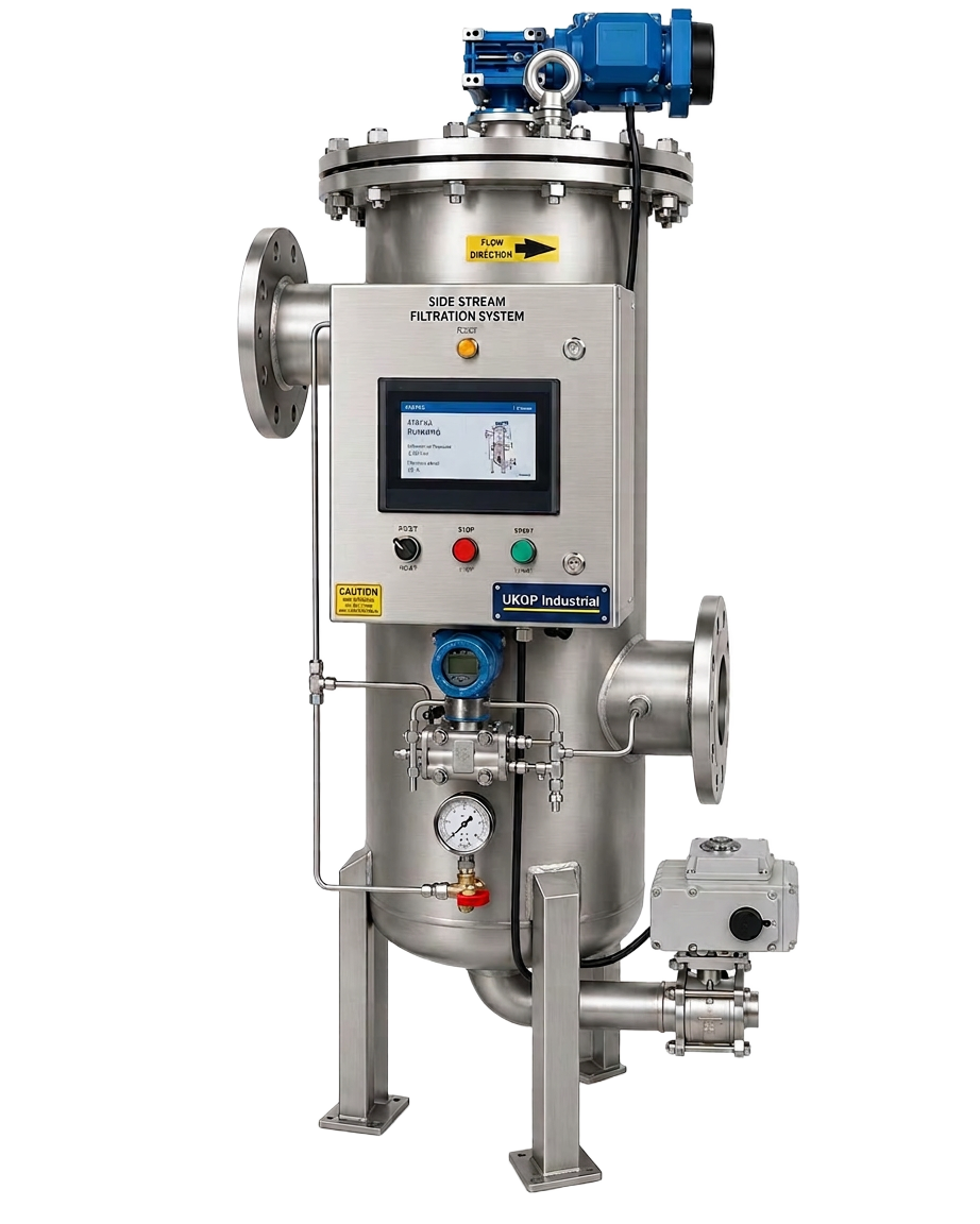
- Consider the use of side stream filtration for high-volume secondary loops.
Primary and secondary pump selection for the header
Pump sizing is arguably the most complex variable in any low loss header installation. The primary pump must be capable of overcoming the resistance of the boiler and primary pipework while maintaining the manufacturer’s minimum flow rate. Conversely, the secondary pumps are sized based on the resistance of the distribution circuits, such as AHUs or heat emitters. Because the header creates a zone of zero pressure drop, these two pumping systems can operate without hydraulically fighting each other, provided they are commissioned correctly.
The use of variable speed drives (VSDs) on secondary pumps is standard in modern BREEAM-certified buildings to reduce energy consumption. However, these varying flow rates can cause the 'balance' of the low loss header to shift frequently between surplus and deficit flow. A well-executed low loss header installation accounts for these fluctuations by ensuring the vessel has sufficient buffer volume. This prevents 'short-circuiting', where the return temperature to the boiler becomes too high, causing the boiler to modulate down or shut off before the building's heat demand has been satisfied.
For engineers, checking the pump curves against the header's flow capacity is a non-negotiable step. If the secondary pumps collectively move more water than the primary pump, the header will experience a temperature drop as return water is mixed with flow water. This is known as a 'mixing' header. Understanding whether your design requires a 'mixing' or 'bypass' characteristic is the difference between a high-performing system and a failing one. UKGP Industrial offers technical support to help match our 40-2000 kW headers to your specific pump duties and head requirements.
- Select primary pumps to meet boiler-specific Delta T requirements.
- Use VSD pumps on secondary circuits to improve energy efficiency.
- Monitor flow rates to ensure primary flow exceeds secondary flow for condensing.
- Verify pump head calculations to account for header internal resistance.
Maintaining water quality and chemical dosing
A low loss header installation is only as good as the water running through it. To prevent corrosion within the header and the wider system, chemical dosing is mandatory under BS 8552. A dosing pot should be installed to introduce inhibitors that protect the diverse range of metals found in industrial HVAC systems, from the carbon steel of the header vessel to the copper or stainless steel in the heat exchangers. Without proper chemical treatment, the neutral zone of the header can become a site for localised corrosion.
In addition to inhibitors, pH monitoring is vital, especially in systems with aluminium heat exchangers which are sensitive to high alkalinity. Integrating sensors that provide real-time data back to the BMS can alert facility managers to shifts in water chemistry before they cause irreversible damage. When planning your low loss header installation layout, ensure there is sufficient space for these peripheral water treatment components. A neglected system will eventually lead to the fouling of the header's internal surfaces, increasing turbulence and reducing its effectiveness as a hydraulic separator.
UKGP Industrial provides a full suite of ancillary equipment, including chemical dosing pots and sensors, to complement our low loss header range. By sourcing all plant room components from a single UK supplier, contractors can ensure that threads and flange ratings match perfectly, reducing the risk of leaks during commissioning. Our low loss headers are delivered within 2-3 weeks, complete with insulation, making them a 'plug-and-play' solution for contractors who need to maintain high standards of water quality management while meeting strict project deadlines.
- Install a dosing pot for the introduction of corrosion inhibitors.
- Monitor pH levels regularly to protect sensitive heat exchangers.
- Schedule annual water analysis to comply with BS 8552.
- Flush the header's settlement zone periodically to remove sludge.
Commissioning and long-term maintenance of the header
The final stage of a low loss header installation is commissioning, where flow rates are balanced to ensure the system operates as designed. Using commissioning valves (metering stations) on both the primary and secondary sides allows engineers to verify that the flow across the header is balanced. This is the moment where any errors in pipework or pump sizing become apparent. A correctly commissioned header will show a clear temperature differential between the flow and return ports, indicating that the boiler is receiving cool enough water to remain in condensing mode.
Long-term maintenance is simplified by the design of the UKGP low loss header. Because the unit is supplied with an insulation jacket, inspecting the vessel for external corrosion or leaks requires minimal effort. The 2-year warranty provides peace of mind for procurement leads who need to justify the capital expenditure on high-specification plant. Engineers should check the integrity of the air vents and drain valves at every service interval to ensure the header continues to function as a de-aerator and dirt collector, protecting the high-value boilers upstream.
In summary, the quality of your low loss header installation dictates the overall efficiency of the commercial heating system. From selecting the correct 40-2000 kW capacity to ensuring the PN16 flanges are correctly torqued, every detail matters. If you are currently designing a plant room or managing an M&E retrofit, contact UKGP Industrial for a quote. Our British-manufactured headers are engineered for performance, durability, and compliance with the latest CIBSE and BSRIA guidelines, ensuring your project meets its energy targets and operational lifespan.
- Perform hydraulic balancing to verify the neutral pressure point.
- Check insulation jackets for proper fit to minimize heat loss.
- Review BMS data to ensure the boiler maintains condensing temperatures.
- Verify that all secondary pumps are responding correctly to zone demands.
Frequently asked questions
What is the primary benefit of a low loss header?
- The primary benefit is hydraulic separation, allowing the primary boiler circuit and secondary distribution circuits to operate at different flow rates and pressures, which prevents pump conflict and protects the boiler.
What size low loss header do I need for a 500kW system?
- For a 500kW system, you need a header sized to handle the maximum combined flow rate of your pumps at a low internal velocity. UKGP provides models from 40kW up to 2000kW to cover these requirements.
Can UKGP low loss headers be used in high-pressure systems?
- Yes, our headers are available with PN16 flanged connections, making them suitable for commercial and industrial high-pressure applications where standard BSP threaded fittings may not suffice.
Does a low loss header require insulation?
- Absolutely. To comply with UK Building Regulations and maximize energy efficiency, all headers should be insulated. UKGP units come with a tailored insulation jacket as standard.
What is the typical lead time for a UKGP header?
- We typically offer a lead time of 2-3 weeks for our standard commercial low loss headers, ensuring that your HVAC installation project stays on schedule.