The Fundamentals of a Low Loss Header Diagram
A low loss header diagram serves as the foundational blueprint for achieving hydraulic decoupling within a multi-circuit heating system. In commercial HVAC environments, the primary circuit (the heat source) often carries different flow requirements compared to the secondary circuits (the emitters). Without a clear low loss header diagram to guide the installation, these distinct circuits can create variable pressure zones that lead to inefficient heat transfer and mechanical stress. The diagram illustrates how the header acts as a vessel of neutral pressure, allowing the primary and secondary pumps to move water at their respective design flow rates without impacting one another. This is essential for protecting modern, high-efficiency condensing boilers which are increasingly sensitive to flow variations.
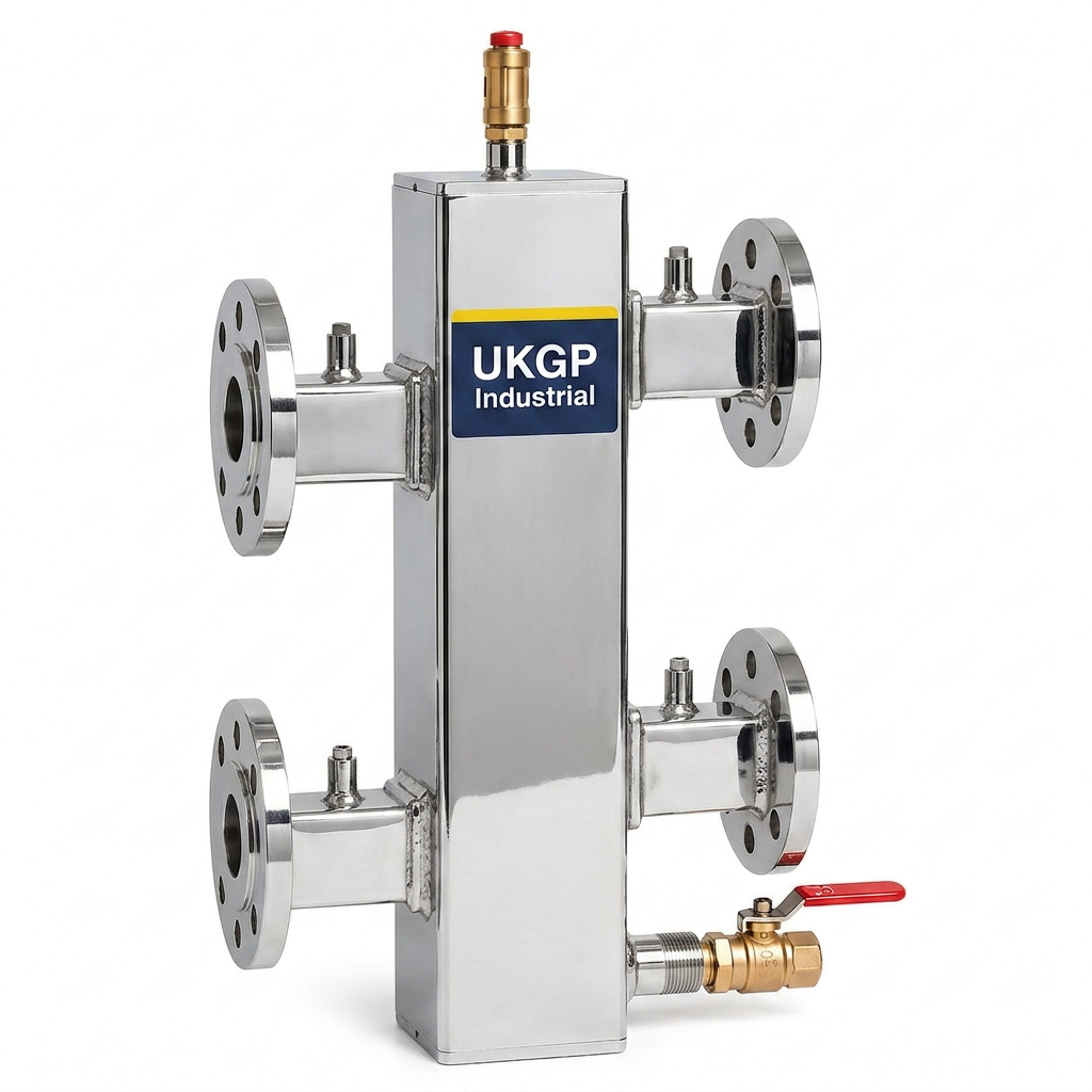
When examining a professional low loss header diagram, you will notice the four-port configuration typically used in flanged or threaded vessels. The 'low loss' name refers to the minimal pressure drop across the body of the header, which is achieved through a large internal cross-sectional area. By reducing the velocity of the water as it enters the vessel, the head pressure from the primary pump is effectively dissipated before it can interfere with the secondary pumps. This design ensures that the system is compliant with CIBSE AM14 guidelines regarding non-interactive circuits. Our UKGP Industrial units are designed to accommodate these high-demand scenarios, supporting systems from 40 kW up to 2000 kW, ensuring that your real-world installation matches the efficiency promised by your initial hydraulic drawings.
Precision in the low loss header diagram is also critical for the integration of sensors and thermal management. Most diagrams will show a thermowell or sensor pocket located in the top section of the header to monitor the flow temperature arriving from the boiler. This allows the building management system (BMS) to modulate the burner correctly based on the temperature present at the point of distribution. For procurement leads and facility managers, ensuring that the physical hardware reflects the technical diagram is the only way to safeguard the 2-year warranty and long-term performance standards expected in UK commercial developments. At UKGP, we provide flanged or threaded BSP/PN16 headers that offer exactly this level of predictable, repeatable performance across all industrial scales.
- Visualises the decoupling of primary and secondary circuits.
- Identifies the location of air vents and drain valves for maintenance.
- Shows the exact positioning for BMS temperature sensors.
- Facilitates compliance with CIBSE and BSRIA best practices.
Hydraulic Separation and Pump Synchronisation
In any complex mechanical layout, the low loss header diagram must clearly define the direction of flow and the neutral point of the system. If the secondary pump flow exceeds the primary pump flow, a portion of the return water is mixed with the flow water within the header, effectively reducing the flow temperature to the emitters. Conversely, if the primary flow is higher, the return temperature to the boiler increases. A well-constructed low loss header diagram identifies these three distinct flow conditions: balanced flow, bypass flow, and induction flow. Each state has a different impact on the condensing efficiency of the boilers, and visualising these paths helps plant room engineers avoid commissioning errors that could lead to premature component failure.
Furthermore, the integration of secondary pumps requires careful consideration of the pump head versus the vessel resistance. The low loss header diagram depicts where the secondary pumps draw suction, which must be downstream of the header to ensure they are not fighting the primary circulating pump. This architectural separation is what permits variable speed pumps to modulate according to zone demand without causing the primary boiler pump to hunt or trip. For consultants designing to BS EN 12828 standards, the diagram provides a checklist for ensuring that the hydraulic resistance of the header is kept to a minimum, typically below 1.0 kPa, which is a standard feature of the UKGP Industrial range of headers.
Maintaining the integrity of these flow paths is also a requirement for meeting BSRIA BG50 standards for water quality. While the header acts as a hydraulic junction, it can also serve as a low-velocity zone where debris can settle. Therefore, the low loss header diagram often includes a bottom-mounted drain valve and a top-vent for air release. By following the flow paths dictated by the diagram, contractors can ensure that sediment does not accumulate in the heat exchangers of expensive boiler plant. UKGP Industrial low loss headers include a removable insulation jacket as standard to prevent heat loss at this critical junction, ensuring that the energy flow remains as efficient as the hydraulic flow.
- Prevents pump conflict and 'ghost' flow in inactive zones.
- Allows for independent modulation of primary and secondary circuits.
- Minimises pressure drops to under 1.0 kPa for energy efficiency.
- Ensures the system operates within defined BSRIA water quality parameters.
The Role of Air and Dirt Removal in the Header Circuit
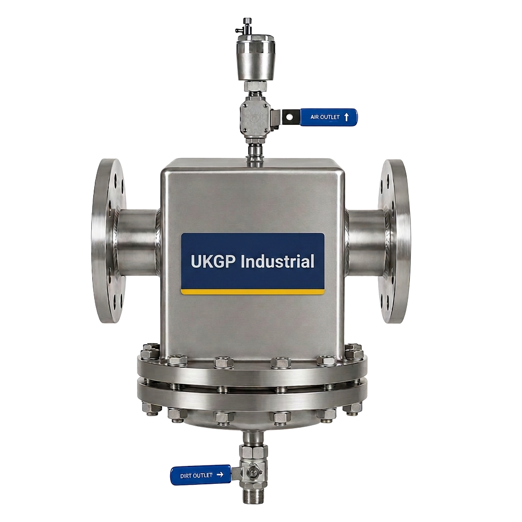
While a low loss header diagram focuses on flow and pressure, the physical environment often necessitates additional components to protect the system's longevity. Specifically, the introduction of an air and dirt separator adjacent to the header is a common best-practice recommendation found in BSRIA BG29 pre-commission cleaning guides. The diagram will typically place these separators on the primary return to the boiler or the common return from the secondary circuits. By capturing micro-bubbles and magnetite before they reach the header, you ensure that the neutral zone remains clean and that the low-velocity benefits are not compromised by sludge accumulation which could disrupt the internal laminar flow paths.
A comprehensive low loss header diagram will show how these auxiliary components interact with the main header. For instance, if the header itself does not feature an internal baffle, an external separator becomes mandatory to meet BS 8552 sampling requirements. Integrating these into the CAD drawing or BIM model ensures that the plant room footprint is managed correctly. M&E contractors must verify that there is sufficient clearance for blow-down valves and magnetic rod removal. UKGP supplies a range of high-performance air & dirt separators that perfectly complement our 40-2000 kW low loss headers, helping to maintain the system transparency required for consistent thermal performance over the decades.
The presence of these components on your technical submittals demonstrates a commitment to operational excellence. When a project moves from a theoretical low loss header diagram to a physical installation, the quality of the finish matters. Our equipment, available with BSP or PN16 flanged connections, ensures a leak-free integration with separators and dosing pots. By following a rigorous diagram that includes dedicated filtration paths, you reduce the risk of erratic sensor readings and ensure that the pH sensors and transmitters in the system provide accurate data to the BMS, ultimately protecting the 2-year warranty offered on our core header products.
- Reduces the risk of magnetite build-up in boiler heat exchangers.
- Enhances the accuracy of monitoring sensors within the header.
- Aligns with BSRIA BG29 guidelines for closed-loop system hygiene.
- Provides clear service access points for FM maintenance teams.
Sizing and Specifying from a Low Loss Header Diagram
Moving from a conceptual low loss header diagram to a bill of materials requires precise calculation of the maximum possible system flow rate. The header must be sized based on the 'worst-case' scenario—usually when all secondary circuits are demanding full load. If the header is undersized relative to the diagram's flow paths, the water velocity will remain too high, and the 'low loss' benefit is lost, leading to hydraulic coupling and potential pump damage. Conversely, an oversized header is a wasted capital expense. UKGP Industrial provides models ranging up to 2000 kW, ensuring that whether you are working on a small commercial unit or a large district heating scheme, the hardware matches the engineering requirements exactly.
Consultants should also check the low loss header diagram for connection types, as this impacts the installation time and cost. Small systems may utilise BSP threaded connections, while larger industrial applications above 50mm typically require PN16 flanged connections for structural integrity. The insulation jacket is another critical specification often overlooked in basic diagrams; without it, the header becomes a massive radiator, losing heat to the plant room and reducing the overall EER of the building. UKGP includes high-quality jackets with every header, ensuring that the design intent of the hydraulic model is matched by the thermal efficiency of the physical installation.
Delivery schedules are a final practical consideration when translating a low loss header diagram into reality. High-spec plant room components can often have long lead times that disrupt a project's critical path. UKGP Industrial bridges this gap by offering a 2-3 week lead time on our commercial headers. This allows M&E contractors to maintain momentum on site without compromising on the technical standards established in the initial design. Whether you require a standard vertical header or a bespoke configuration, our UK-based support ensures that the product arriving on-site matches the flanged or threaded specifications of your verified drawings.
- Sized for 40-2000 kW capacities to suit any commercial project.
- Available in PN16 flanged or BSP threaded options.
- Includes a 2-year warranty for peace of mind on technical builds.
- Fast 2-3 week lead times to keep M&E projects on schedule.
Troubleshooting Using the Low Loss Header Diagram
When a system fails to deliver heat to specific zones, the low loss header diagram is the first tool a maintenance engineer should reach for. If the secondary flow temperatures are significantly lower than the primary flow temperature despite the boilers firing at 100%, the diagram can help identify if the flow rates are imbalanced. This 'mixing' effect happens within the header and can be diagnosed by checking the temperature sensors at each of the four ports shown on the diagram. If the return from the secondary is significantly cooling the flow from the primary, it often indicates that the secondary pumps are oversized or the primary flow is restricted.
Another common issue diagnosed via the low loss header diagram is air binding. If the diagram shows the high point of the header is not equipped with an automatic air vent (AAV), air can become trapped in the vessel, creating a noise nuisance and reducing the effective diameter of the flow path. This increases the pressure drop across what should be a low-loss component. By comparing the physical installation against the idealised diagram, engineers can quickly identify where additional venting or dirt removal is required to restore the system to its design parameters, ensuring the plant room remains quiet and efficient.
Finally, the low loss header diagram assists in verifying the correct installation of the expansion bellows and low loss headers in relation to fixed points. Thermal expansion can put significant stress on the header's flanges if not properly managed. By observing the flow paths and temperature gradients on the diagram, engineers can determine where the greatest thermal movement will occur. UKGP Industrial headers are built to withstand these stresses, but following a correct hydraulic layout is essential for ensuring that the BSP or PN16 joints remain secure. Requesting a quote for a UKGP header ensures you receive a product designed for these high-stress industrial environments.
- Aids in diagnosing flow imbalances and mixing issues.
- Identifies missing components like AAVs or drain cocks.
- Assists in assessing thermal expansion risks at flange joints.
- Simplifies the commissioning process for plant room engineers.
Compliance with British Standards and BSRIA
Adhering to a technical low loss header diagram is not just about functionality; it is about regulatory compliance. In the UK, the design and installation of pressure vessels and hydraulic separators must meet specific safety and performance benchmarks. BS EN 12828 is the primary standard for the design of water-based heating systems, and it clearly mandates the use of hydraulic separation in systems where primary and secondary circuits have different flow requirements. By utilising a UKGP low loss header that is manufactured to these standards, you ensure that your project meets the rigorous requirements of building control and insurance providers.
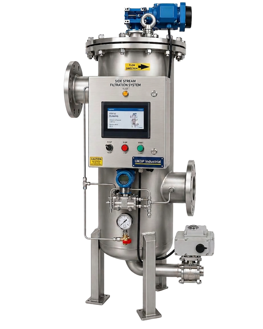
Compliance also extends to the water quality standards set out in BSRIA BG50 and BS 8552. The low loss header diagram plays a role here by providing the ideal location for chemical dosing pots and side stream filtration units. If the diagram shows a clear side stream path, it becomes much simpler for a contractor to install the necessary equipment to prevent corrosion and scale. UKGP low loss headers are designed to hold a stable volume of water, which helps in maintaining the chemical concentration levels required for ongoing protection of the system, further supported by our 2-year warranty on all header units.
Lastly, we must consider the environmental impact. A correctly implemented low loss header diagram ensures that the heat source operates at the lowest possible return temperature, which is essential for maximizing the seasonal efficiency of condensing boilers and heat pumps. This directly impacts the building's EPC rating and operational costs. For procurement leads, choosing a UKGP Industrial 40-2000 kW header is a strategic decision that supports both technical compliance and commercial sustainability. Contact us today to receive a detailed specification and quote for your next project, benefiting from our industry-leading 2-3 week lead times.
- Fully compliant with BS EN 12828 hydraulic design standards.
- Supports BG50 and BS 8552 water quality management strategies.
- Enhances boiler condensing through improved return temperatures.
- Ensures long-term reliability for commercial and industrial assets.
Frequently asked questions
Why is a low loss header diagram essential for commercial HVAC?
- It ensures that the primary and secondary pumping systems are hydraulically separated, preventing pump conflict and ensuring correct flow rates to both the heat source and emitters.
What flow conditions are shown in a low loss header diagram?
- Diagrams typically show three conditions: balanced flow (equal primary and secondary), bypass flow (primary exceeds secondary), and induction flow (secondary exceeds primary).
Where should the temperature sensor be placed on the header?
- A standard low loss header diagram places the sensor pocket in the flow section at the top of the header to provide the most accurate reading for the BMS.
What is the typical lead time for a UKGP low loss header?
- UKGP Industrial offers an industry-leading lead time of 2-3 weeks for our commercial headers, which range from 40 kW to 2000 kW and include an insulation jacket.
Does a low loss header replace an air and dirt separator?
- While it can facilitate some separation, a dedicated air and dirt separator is usually shown on the diagram to meet BSRIA BG29 water quality standards.