The Fundamental Physics of Low Loss Header Design
In modern commercial heating installations, the low loss header design functions as a neutral point of pressure, effectively decoupling the primary energy source from the secondary heating loads. When multiple boilers or heat pumps are piped in sequence, variations in flow velocity can lead to hydraulic interference, where pumps effectively fight against one another. This interference reduces the operational lifespan of circulators and can cause significant temperature fluctuations at the tertiary distribution level. By introducing a header with a correctly calculated internal volume, the pressure drop across the vessel becomes negligible, allowing the primary and secondary pumps to operate at their respective design flow rates without affecting the counterpart's performance.
A critical aspect of a professional low loss header design is how it manages the mixing of return water and delivery water under varying load conditions. CIBSE guidelines and BSRIA BG29 highlights the importance of maintaining low vertical velocities within the header—typically below 0.5 meters per second—to allow for the natural stratification of temperature and the effective trapping of air and dirt. This velocity control is achieved by carefully sizing the vessel diameter relative to the pipework entering it. Without this careful consideration during the design phase, the vessel may fail to decouple the circuits correctly, leading to 'ghost' flow or inadequate heat transfer to the building's emitters, ultimately compromising the system's overall seasonal efficiency.
Furthermore, the integration of a well-engineered header supports the longevity of highly efficient condensing boilers. By ensuring that the return water temperature is managed correctly through hydraulic separation, the low loss header design helps maintain the high delta-T necessary for condensing to occur. When specifying these vessels for a Surrey or London-based project, M&E contractors must look for units that offer not just the volume, but the structural integrity to withstand system pressures over time. UKGP Industrial provides these solutions for capacities ranging from 40 kW to 2000 kW, ensuring that from small commercial units to large district heating hubs, the hydraulic integrity of the plant room remains constant and predictable for the facility management team.
- Achieves full hydraulic decoupling of primary and secondary circuits.
- Reduces vertical water velocity to below 0.5m/s for optimal performance.
- Protects expensive boiler heat exchangers from erratic flow pressures.
- Ensures stable operation of variable speed pumps across the network.
The 3:1 Rule and Port Placement Specifications
The most widely accepted standard in low loss header design revolves around the '3:1 rule,' which dictates that the diameter of the header vessel should be three times the diameter of the primary supply pipework. This ratio is not arbitrary; it is meticulously calculated to ensure that the cross-sectional area of the header is sufficient to reduce the kinetic energy of the incoming fluid. When the water moves from the narrow primary pipe into the larger volume of the header, its velocity drops significantly, creating a zone of low pressure where the primary and secondary pumps can coexist. Adherence to this ratio prevents turbulent mixing and ensures that the bypass remains hydraulically neutral, regardless of whether the secondary demand is higher or lower than the primary supply.
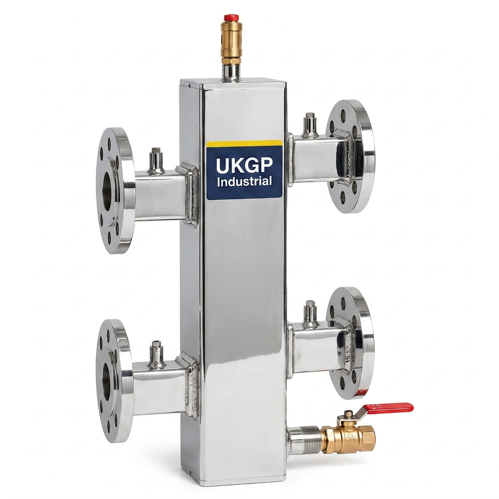
Port placement is the second pillar of an effective low loss header design. Standard configurations usually involve four main ports: two for the primary circuit and two for the secondary circuit. For optimal results, these ports should be offset to encourage the separation of air and the settlement of debris. The primary flow and secondary flow ports are typically located at the top of the vessel, while return ports are located mid-to-bottom. BSRIA BG50 recommendations suggest that the spacing between the ports should be sufficient to prevent high-velocity 'jetting' from one port directly into another, which would negate the purpose of the decoupling vessel and lead to unintended temperature blending that hinders system performance.
Incorrect port alignment or an undersized header body often results in a 'short-circuit' where water bypasses the secondary loop entirely or flows backward through the header. This is a common maintenance headache for facility managers that can be avoided at the procurement stage. When sizing your system, ensure the low loss header design incorporates the appropriate flange or thread connections for your specific pipework. UKGP Industrial offers both flanged (PN16) and threaded (BSP) options for our headers, which are designed specifically to meet these 3:1 volumetric requirements. Our technical team can assist in verifying that the port orientation of your selected unit matches the physical constraints of your plant room while maintaining these critical engineering ratios.
- Strict adherence to the 3:1 diameter ratio for velocity reduction.
- Staggered port placement to promote debris settlement and air removal.
- Compatibility with both BSP threaded and PN16 flanged connections.
- Mitigation of turbulence to preserve stratified temperature zones.
Integration with Air and Dirt Separation
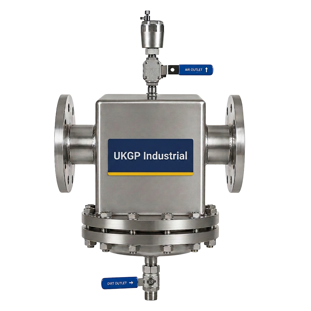
While the primary purpose of low loss header design is hydraulic separation, it inadvertently provides an ideal environment for secondary water treatment functions. Because the water velocity drops significantly inside the vessel, heavy particulate matter tends to fall to the bottom of the header, while air bubbles rise to the top. Many engineers choose to specify headers with a dedicated drain valve at the bottom and an automatic air vent at the highest point. This proactive approach aligns with BSRIA BG29 and BS 8552 guidelines regarding the maintenance of water quality in closed-loop systems, reducing the risk of erosion and blockages in high-value components like plate heat exchangers or control valves.
In larger systems where the header volume alone might not be sufficient for complete filtration, it is common to install a dedicated air and dirt separator upstream. However, a high-quality low loss header design will always include internal features to aid this process, such as baffles or magnetic inserts. By stripping microbubbles and magnetite from the system flow within the header, the efficiency of heat transfer across the entire building is improved. This is particularly important in systems utilizing modern, small-bore heat exchangers which are highly susceptible to clogging. Effectively managing these contaminants reduces the frequency of emergency call-outs and ensures that the commercial heating system meets its design life expectations.
For consultants designing high-performance plant rooms, combining a UKGP low loss header with our air and dirt separators can provide a comprehensive solution for system protection. This holistic approach ensures that the fluid entering the secondary distribution network is both hydraulically stable and free from harmful debris. When you request a quote for our headers, consider the total system health; our units come with a 2-year warranty and are manufactured to withstand the rigours of UK commercial environments. These headers are available with a lead time of just 2-3 weeks, allowing your project to stay on schedule while meeting the highest technical standards of debris management and air elimination.
- Integrated drain points for easy removal of settled sludge.
- Upper venting ports for the installation of automatic air eliminators.
- Compliance with BSRIA BG29 water quality management standards.
- Improved heat transfer efficiency by removing microbubbles and magnetite.
Thermal Management and Insulation Jackets
A superior low loss header design is not complete without rigorous attention to thermal efficiency. Because headers act as a hub for hot system water, they can become a significant source of standing heat loss if left uninsulated. This is not only a waste of energy but can also lead to excessive ambient temperatures in the plant room, potentially overheating sensitive electronic controllers or pumps. Specifying a header with a custom-fit, high-performance insulation jacket is essential for compliance with CIBSE energy efficiency guidelines and Part L of the Building Regulations. These jackets should be easily removable to facilitate periodic inspections of the vessel's shell and connections.
UKGP Industrial provides high-quality insulation jackets with our commercial low loss headers (40-2000 kW). These jackets are designed to minimize convective and radiant heat loss, ensuring that the energy produced by the boilers is delivered where it is needed—to the building occupants. The insulation is tailored to the specific dimensions of our flanged and threaded units, providing a professional finish that is both functional and aesthetically pleasing. For facility managers, having a neatly insulated header means lower operational costs and a safer working environment for maintenance staff who might otherwise be exposed to hot metal surfaces while working in confined plant room spaces.
Beyond simple heat retention, the insulation within a low loss header design serves to prevent condensation in cooling applications. While primarily used in heating, headers can be adapted for chilled water systems to decouple chillers from the distribution circuit. In these cases, the insulation jacket must be vapour-sealed to prevent moisture from reaching the vessel's surface, which could lead to external corrosion over time. Whether for a heating or cooling application, our UKGP headers are built to last, featuring a robust construction and a 2-year warranty that gives M&E contractors and procurement leads peace of mind that their hydraulic separation solution is built for the long term.
- Removable insulation jackets included to minimize standing heat loss.
- Compliance with CIBSE and Part L energy efficiency requirements.
- Protection against high plant room ambient temperatures and accidental burns.
- Vapour-sealable options for chilled water decoupling applications.
Sizing Calculations and Pressure Drop Considerations
Determining the correct size during the low loss header design phase requires a precise understanding of the system's maximum flow rate (Q). The vessel must be sized based on the larger of the two flow rates: the primary circuit or the secondary circuit. A common error is sizing the header based on the connection size of the boilers alone, which may not account for the total peak demand of the distribution network. Using the formula for volumetric flow and the target velocity of 0.5m/s, engineers can calculate the required cross-sectional area. If the header is sized too small, the high velocity will cause mixing, resulting in a temperature drop that prevents the system from reaching its set point.
Pressure drop is another critical factor. A correctly executed low loss header design should provide almost zero resistance to flow. This ensures that the head generated by the primary pumps is spent entirely on circulating through the heat source, while the secondary pumps focus solely on the building's zones. Measuring the pressure differential across the header during commissioning can confirm if the 3:1 ratio is performing as expected. If a significant pressure drop is detected, it usually indicates that the vessel is undersized or that internal blockages are occurring. This is why following BS EN 14917 guidelines for vessel construction and BSRIA standards for pipework sizing is non-negotiable for professional installations.
At UKGP Industrial, we simplify this process by offering a range of pre-engineered low loss headers for 40 kW to 2000 kW applications. Each unit is manufactured with standardized dimensions that have been proven to deliver the necessary hydraulic neutrality for varied commercial loads. By choosing a UKGP unit, engineers can bypass the complex bespoke fabrication process and rely on an off-the-shelf solution that meets all technical criteria for port spacing and volumetric capacity. With a 2-3 week lead time, you can secure a high-performance header that integrates seamlessly into your M&E project, backed by our specialist technical support and a comprehensive 2-year warranty.
- Size vessels based on the maximum anticipated flow rate, not pipe size.
- Maintain zero-pressure neutrality to avoid pump performance conflicts.
- Verify design logic against BS EN and BSRIA standards for plant rooms.
- Avoid temperature blending issues by adhering to precise velocity limits.
Specifying UKGP Industrial Low Loss Headers
When procurement leads and M&E contractors require a reliable low loss header design, the UKGP Industrial range offers the perfect balance of technical precision and commercial availability. Our units are designed to handle the rigorous demands of modern UK heating systems, providing the hydraulic separation needed for high-efficiency condensing boilers and heat pump arrays. Available in sizes from 40 kW up to 2000 kW, we cater to everything from small office blocks to large industrial complexes. Our headers are available with either BSP threaded connections for smaller applications or PN16 flanged connections for larger, high-pressure systems, ensuring a perfect fit for any pipework specification.
Quality assurance is at the heart of our manufacturing process. Every UKGP low loss header is supplied with a high-grade insulation jacket as standard, helping satisfy the energy performance requirements of today's building services projects. Our commitment to the UK market means we maintain a 2-3 week lead time, significantly faster than many bespoke alternatives, allowing your contractors to stay on schedule during critical plant room fit-outs. Furthermore, each unit is backed by a 2-year warranty, reflecting our confidence in the durability and engineering integrity of our products. This combination of performance and reliability makes UKGP the preferred supplier for consultants across Surrey and the wider UK.
Navigating the complexities of low loss header design doesn't have to be a challenge. Whether you are dealing with a complex multi-boiler retrofit or a new build sustainable heating project, UKGP Industrial has the technical expertise and the hardware to support your goals. Contact our technical sales team today for a competitive quote or to discuss your specific port placement and sizing requirements. We are dedicated to providing the high-specification components—from dosing pots to air and dirt separators—that ensure your HVAC systems operate with peak efficiency and minimal maintenance for years to come. Choose UKGP for engineering excellence and rapid delivery to your site.
- Standardized ranges from 40 kW to 2000 kW for all commercial scales.
- Choice of BSP or PN16 flanged connections for easy installation.
- Rapid 2-3 week lead times to keep M&E projects on schedule.
- Comprehensive 2-year warranty and high-quality insulation included.
Frequently asked questions
What is the 3:1 rule in low loss header design?
- The 3:1 rule states that the diameter of the low loss header vessel should be three times the diameter of the primary supply pipework. This ensures the water velocity drops sufficiently to create a hydraulically neutral zone.
Why is port placement important in a low loss header?
- Correct port placement prevents 'jetting' where high-velocity water bypasses the neutral zone. Offset ports also assist in the natural separation of air and debris, aligning with BSRIA BG29 water quality standards.
Can I use a low loss header with a heat pump?
- Yes, a correct low loss header design is essential for heat pumps to maintain the high flow rates they require, preventing them from being restricted by the narrower, slower-moving secondary heating circuits.
What connections are available on UKGP headers?
- UKGP headers are available with BSP threaded connections for smaller loads or PN16 flanged connections for larger commercial systems (up to 2000 kW), providing flexibility for all M&E requirements.
Do UKGP low loss headers come with insulation?
- Yes, all our commercial low loss headers are supplied with a bespoke, removable insulation jacket to minimize heat loss and ensure compliance with energy efficiency regulations.