The fundamentals of thermal expansion in piping
In any closed-loop heating or chilled water system, temperature fluctuations cause physical changes in pipe length that can lead to catastrophic failure if not properly managed. When a copper or carbon steel pipe is heated, the kinetic energy of the atoms increases, resulting in longitudinal expansion that exerts immense force on anchors, guides, and connected equipment. Failing to perform a rigorous expansion bellows calculation during the design phase often leads to buckled pipework or flange leaks, which can disrupt site operations and increase maintenance overheads for facility managers. CIBSE Guide C provides the standard coefficients of thermal expansion required to begin these assessments accurately across different material types and operating temperatures.
To calculate the total movement, an engineer must first identify the installation temperature and the maximum projected operating temperature. The difference between these two points, known as the delta T, is the primary driver of expansion. For example, a low-pressure hot water system might be installed at 10 degrees Celsius but operate at 82 degrees Celsius. By applying the linear expansion formula, which involves multiplying the pipe length by the delta T and the material's specific expansion coefficient, you derive the total millimetres of growth. This figure is the foundation for selecting an expansion joint that can handle the specific stroke without exceeding its cyclic life design limits, as specified in BS EN 14917.
Beyond linear growth, one must also account for a safety margin, typically recommended at 15 to 25 percent depending on the complexity of the pipe run and the sensitivity of the connected plant such as chillers or boilers. British Standards and BSRIA BG50 guidelines emphasize that thermal movement management is not just about pipe integrity but also about protecting expensive components from mechanical stress. When you initiate an expansion bellows calculation, you are essentially performing a risk assessment for the entire mechanical infrastructure. Ensuring this calculation is correct prevents the transfer of loads to pump casings and heat exchanger nozzles, which are often the weakest points in a pressurised fluid system.
- Identify the coefficient of linear expansion for the specific pipe material.
- Determine the maximum and minimum system temperature extremes.
- Calculate the total linear growth over the longest unrestrained pipe run.
- Apply a safety factor to account for installation tolerances and surges.
Expansion bellows calculation worked example
Let us consider a practical expansion bellows calculation worked example for a 50-metre run of carbon steel pipework. Carbon steel has a coefficient of expansion of approximately 0.012 mm/m/°C. If the system is installed at an ambient temperature of 15°C and is designed to carry LTHW at 85°C, the temperature differential is 70°C. Squaring this data into our formula—50 metres multiplied by 70 degrees multiplied by 0.012—results in a total linear expansion of 42mm. This value represents the net movement that the expansion joint must absorb through its bellows convolutions without overstressing the material or reaching its physical compression limit, making accurate measurement vital for procurement leads.
Once the 42mm movement is established, the engineer must then select a bellows unit capable of this range. At UKGP Industrial, we provide units designed for various movement capacities, but in this specific example, a bellows rated for at least 50mm of axial compression would be the safest choice. This ensures that even if local temperatures exceed the design parameters slightly, the bellows remains within its elastic region. It is also important to consider the 'cold pull' or pre-setting of the bellows during installation. Pre-setting can allow a single unit to handle more total movement by stretching it during installation so it moves through a neutral point into compression during operation, effectively doubling the usable stroke.
Finalising the expansion bellows calculation also requires a check on the anchor loads. The force exerted on the main anchors is a combination of the bellows spring rate multiplied by its deflection, plus the pressure thrust. Pressure thrust is the internal pressure of the system multiplied by the effective cross-sectional area of the bellows. For a DN100 pipe at 10 bar, this force can be substantial, often reaching several tonnes. M&E contractors must ensure that the building structure and the pipe supports are capable of resisting these resultant forces. Without this secondary calculation, the anchor points may fail, regardless of how high-quality the expansion joint itself is during service.
- Step 1: Calculate Delta T (Temp Max - Temp Install).
- Step 2: Multiply Length x Delta T x Expansion Coefficient.
- Step 3: Add the 20% safety margin to the result.
- Step 4: Select a UKGP unit that exceeds the calculated movement.
Selecting the right material for the application
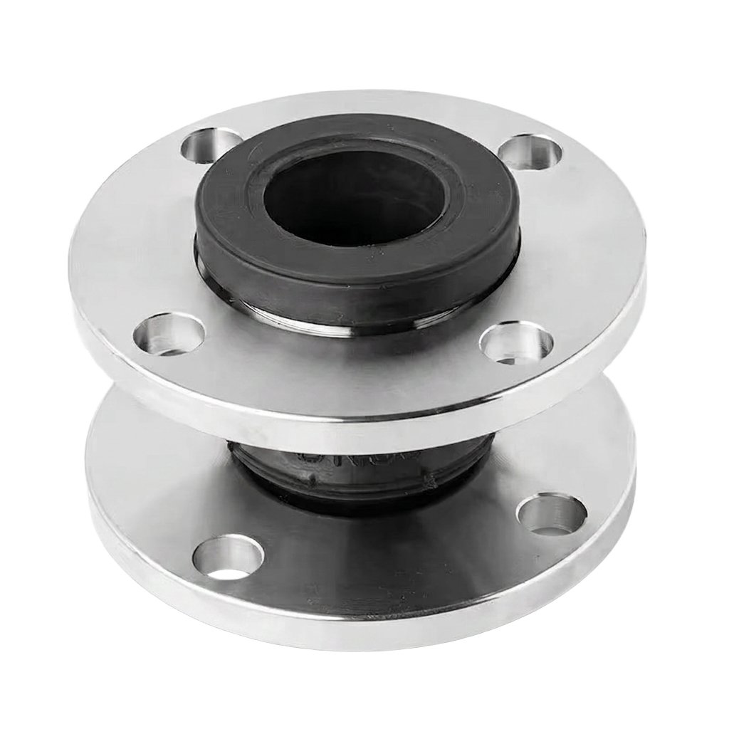
After completing your expansion bellows calculation, the next commercial and technical decision involves material selection. UKGP Industrial manufactures bellows in a variety of materials including EPDM and NBR rubber, stainless steel, PTFE, and high-temperature fabrics. For standard HVAC LTHW and CHW systems, EPDM rubber bellows are often the most cost-effective solution, providing excellent vibration isolation alongside thermal movement absorption. However, for higher pressure or temperature steam applications, stainless steel 316L or 321 bellows are mandatory to comply with BS EN 14917. These metallic units offer the durability required for aggressive environments and higher cycle counts required in critical infrastructure projects.
Chemical compatibility is another crucial factor that must be cross-referenced with your calculation results. While the calculation tells you 'how much' the pipe moves, the fluid medium tells you 'what' the bellows should be made of. For instance, in systems where oil or hydrocarbons are present, NBR (Nitrile) is preferred over EPDM to prevent material degradation. In highly corrosive chemical processing lines, PTFE-lined expansion joints provide the necessary resistance while still offering the flexibility required to take up the calculated expansion. UKGP’s technical team can help you match the outputs of your expansion bellows calculation with the exact material specification needed for your specific project environment.
Our range spans from DN15 to DN600, available with flanged or weld-end connections to suit your piping preference. All UKGP expansion bellows come with a 2-year warranty, providing peace of mind for procurement leads and facility managers who need to ensure long-term reliability. When you request a quote for our expansion bellows, we don't just supply a part; we provide the technical assurance that the product fits your specific engineering requirements. Whether you require a tied rubber compensator for a pump set or a multi-convolution stainless steel unit for a long-distance district heating main, our stock availability and technical expertise ensure your project stays on schedule.
- EPDM/NBR for standard HVAC and vibration isolation.
- Stainless steel for high-pressure steam and extreme temperatures.
- PTFE and fabric options for specialist chemical or flue gas ducting.
- Sizes available from DN15 to DN600 with multiple connection types.
Anchoring and guiding requirements
The success of any expansion bellows calculation depends entirely on the correct placement of anchors and guides. An expansion joint is a flexible point in a normally rigid system; without proper anchoring, the internal pressure would simply push the pipework apart at the joint. Main anchors must be located at the ends of pipe runs, at changes in direction, and between two expansion joints. These anchors must be designed to withstand the full pressure thrust and the spring rate forces identified in your calculation. BSRIA BG29 and BG50 highlight that poor anchoring is the leading cause of bellows failure in the UK market, often resulting in expensive remedial works and system downtime.
Intermediate guides are equally important to prevent the pipe from bowing or buckling as it expands toward the bellows. If the pipe is not guided in a straight line, the lateral forces can cause the bellows to distort, leading to premature failure of the convolutions. Standard engineering practice dictates that the first guide should be placed within a distance of four pipe diameters from the bellows, and the second guide within fourteen diameters. Subsequent guides are spaced according to the pipe diameter and the internal pressure of the system. This rigid guiding ensures that the movement remains purely axial, which is the most efficient way for the bellows to operate.
For complex plant rooms where space is at a premium, it may be necessary to use 'tied' expansion joints. These units feature tie bars that limit the overall extension of the bellows, preventing it from pulling apart under pressure thrust. However, tied joints are typically used to absorb lateral movement rather than axial expansion. This distinction is critical during the expansion bellows calculation process. If your design requires axial movement absorption, you must ensure the anchors are capable of handling the pressure thrust, as tie bars would render the unit useless for axial compression. Relying on UKGP’s engineering support can help clarify these configurations during the drafting of your piping specification.
- Place main anchors at every change in pipe direction.
- Ensure the first guide is within 4x pipe diameter of the joint.
- Use tie bars only when lateral movement absorption is the priority.
- Verify anchor strength against the calculated pressure thrust.
Integrating bellows with low loss headers and separators
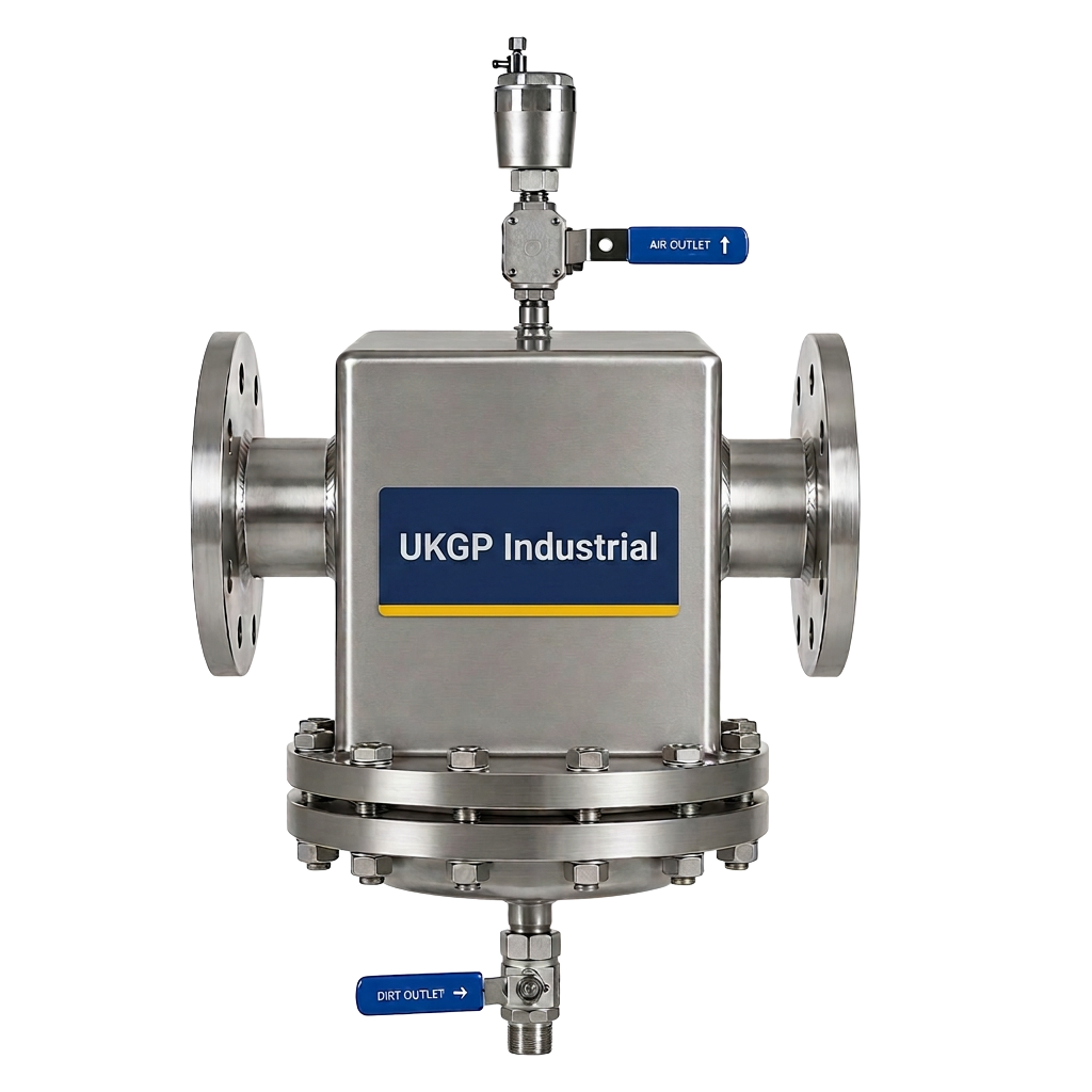
In modern plant rooms, the expansion bellows often sits in close proximity to other critical components like low loss headers and air & dirt separators. These components act as the central distribution and cleaning hubs for the system. When performing your expansion bellows calculation, you must account for the expansion of the headers themselves, especially in large-scale commercial installs where the header might be several metres long. A low loss header facilitates hydraulic separation between primary and secondary circuits, and it is vital that the connections to these headers aren't stressed by migrating thermal expansion from the main distribution loops.
Properly managed expansion ensures that the internal baffles and flow plates within separators and headers remain perfectly aligned. Strain on the nozzles can lead to weeping gaskets or, in extreme cases, cracking of the welds on the vessel itself. By installing UKGP expansion bellows on the flow and return lines leading to a low loss header, you isolate the vessel from the pipework’s thermal growth. This integrated approach to plant room design is a hallmark of high-quality M&E contracting. Combining precision calculation with robust hardware like UKGP's separators ensures the entire system operates at peak efficiency with minimal risk of air ingress or debris build-up.
UKGP offers a comprehensive range of low loss headers and separators that complement our expansion bellows range. When specifying these items together, procurement leads can streamline their supply chain and ensure compatibility across all flanged connections. Our low loss headers are designed to work seamlessly with the thermal profiles calculated in the previous sections, ensuring that as temperatures rise, the mechanical integrity of the plant room remains uncompromised. Requesting a combined quote for bellows, separators, and headers can often provide commercial advantages while guaranteeing that every component meets the same high British standards for manufacture and performance.
- Isolate low loss headers from pipework stress using axial bellows.
- Ensure separators are protected from thermal expansion forces.
- Standardise flanged connections across all plant room components.
- Improve system longevity by reducing mechanical fatigue.
Why accuracy in calculation matters for FMs
For Facility Managers, the repercussions of an incorrect expansion bellows calculation manifest as recurring leaks and unexplained system noise. If a bellows is undersized or the pipe guiding is insufficient, the joint will eventually suffer from fatigue cracking. This not only causes water loss but also allows oxygen to enter the system, leading to corrosion and sludge formation, which contravenes BSRIA BG50 guidelines. An accurate calculation during the refurbishment or initial build Phase ensures that the system remains ‘fit and forget,’ reducing the need for emergency call-outs and unplanned shutdowns that can be both costly and disruptive to building occupants.
Furthermore, an accurately specified system reduces the load on circulating pumps. When pipework is allowed to expand and contract without stress, the friction and mechanical resistance remain within design parameters, allowing pumps to operate at their intended duty point. This directly impacts energy consumption and the carbon footprint of the building. By insisting on a verified expansion bellows calculation, FMs can hold contractors accountable and ensure that the installed hardware—such as UKGP’s flanged EPDM units—is perfectly matched to the actual physical demands of the building's heating and cooling cycles.
At UKGP Industrial, we support engineers and FMs throughout the product lifecycle. From the initial expansion bellows calculation to the final commissioning and long-term maintenance, our technical team is available to provide guidance on BS EN 14917 compliance and best practices. Our bellows, available from DN15 to DN600, are tested to withstand the rigours of UK commercial environments. With a 2-year warranty and a range of materials including stainless steel and PTFE, we provide the reliable hardware needed to back up your engineering calculations. Contact us today to discuss your project requirements or to request a technical data sheet for our expansion solutions.
- Reduce emergency maintenance by preventing fatigue failure.
- Improve energy efficiency by maintaining hydraulic balance.
- Ensure compliance with BSRIA BG50 water quality standards.
- Benefit from the security of a 2-year UKGP product warranty.
Frequently asked questions
What is the standard formula for an expansion bellows calculation?
- The formula is ΔL = L * α * ΔT, where ΔL is the expansion in mm, L is the length of the pipe in metres, α is the coefficient of thermal expansion for the pipe material, and ΔT is the temperature difference between installation and operation.
How many guides are needed for an expansion bellows installation?
- Typically, two primary guides are required close to the bellows. The first guide should be within 4 pipe diameters (4D) and the second within 14 pipe diameters (14D), followed by standard intermediate guiding as per CIBSE or BSRIA recommendations.
Can I use rubber bellows for high-pressure steam systems?
- No, rubber EPDM or NBR bellows are generally limited to lower temperatures and pressures (typically up to 100-110°C). For steam applications, stainless steel expansion bellows manufactured to BS EN 14917 are required to handle the heat and pressure.
What is the benefit of 'cold pulling' a bellows?
- Cold pulling involves pre-stretching the bellows during installation. This allows the unit to use its full range of movement more effectively, often enabling a single joint to handle higher levels of thermal expansion that would otherwise require multiple units or a larger bespoke joint.
Do UKGP expansion bellows come with a warranty?
- Yes, all UKGP expansion bellows (including rubber, stainless steel, and PTFE variants from DN15 to DN600) come with a comprehensive 2-year warranty, ensuring reliability for M&E contractors and facility managers.