The Fundamentals of a 100kw low loss header
In the UK commercial sector, a 100kw low loss header acts as the neutral point in a hydronic system where the velocity of the water is significantly reduced. This reduction in velocity allows the primary circuit, typically consisting of one or more boilers, to operate at a constant flow rate while the secondary circuits fluctuate based on building demand. Without this hydraulic decoupling, modern variable speed pumps on the secondary side can exert pull on the primary side, leading to erratic boiler firing and thermal shock. Using a correctly sized header ensures that the primary and secondary flow rates are independent, protecting the heat source and improving overall energy efficiency across the plant room.
Precision in sizing is non-negotiable for engineers. A vessel that is too small for a 100kW output will fail to provide the necessary 'low loss' environment, resulting in excessive turbulence and pressure drops that negate the benefits of separation. Conversely, an oversized header adds unnecessary cost and thermal mass to the system. UKGP Industrial designs these headers to accommodate the specific delta T (ΔT) requirements of modern condensing boilers, typically aiming for a 20°C temperature difference. This alignment with UK building services standards ensures that the return water temperatures remain low enough to maintain the boiler in condensing mode, further enhancing the seasonal efficiency of the entire heating installation.
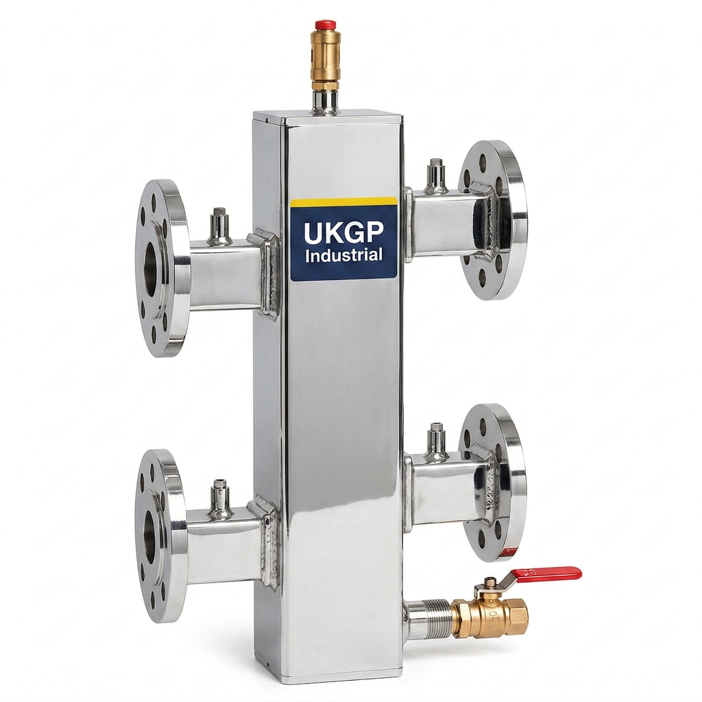
Beyond simple separation, the physical construction of the header plays a vital role in system health. High-quality vessels serve as a collection point for air and debris, which can then be purged via integrated air vents and drain valves. When specifying a unit for a 100kW application, procurement leads should look for robust builds that include thermal insulation jackets as standard. UKGP provides these units with a 2-year warranty and a rapid 2-3 week lead time, ensuring that M&E projects remain on schedule without compromising on technical excellence or hydraulic integrity in the most demanding commercial environments.
- Ensures hydraulic separation between primary and secondary circuits.
- Maintains a neutral pressure zone to prevent pump competition.
- Facilitates easier air and dirt removal within the system.
- Protects high-efficiency heat exchangers from thermal stress.
Calculating Flow Rates for 100kW Systems
Specifying the flow rate for a 100kw low loss header requires a firm grasp of the formula Q = m × Cp × ΔT. For a 100kW load with a standard 20°C temperature drop, the flow rate typically equates to approximately 1.2 litres per second (4.3 m³/h). It is essential that the internal velocity within the header remains below 0.5 metres per second to allow for effective hydraulic decoupling. At higher velocities, the water does not have sufficient dwell time to lose its kinetic energy, which causes the primary and secondary circuits to influence one another. This can lead to the 'lifting' of the return temperature, which prevents condensing boilers from operating at peak efficiency.
Contractors must also account for the physical dimensions of the header to ensure it can handle these calculated volumes. A standard 100kW unit often features 2” (DN50) connections, which are suitable for the flow rates mentioned above without inducing excessive friction losses. For those looking for flexibility in installation, UKGP offers these headers in both threaded BSP and flanged PN16 configurations. Providing a versatile range of connection types allows engineers to integrate the 100kw low loss header into existing pipework or new-build projects with minimal fuss. Ensuring the connections are sized correctly is the first step in maintaining the design velocity targets necessary for the system to remain hydraulically balanced and quiet.
Furthermore, flow rates must be considered during the commissioning phase. BSRIA BG29 and BG50 highlight the importance of maintaining proper flow and chemistry to avoid local stagnation or erosion. If the secondary pump flow exceeds the primary pump flow, the return temperature to the boiler will rise as it mixes with the supply water. If the primary exceeds the secondary, the supply temperature to the building may drop below the design point. A well-specified 100kW header provides the buffer space needed to manage these variances smoothly. UKGP's range of units, rated from 40 to 2000 kW, are specifically engineered to accommodate these transient phases while maintaining the 0.5 m/s velocity rule.
- Target internal water velocity should not exceed 0.5 m/s.
- Standard flow for 100kW at ΔT 20°C is ~4.3 m³/h.
- Available in PN16 flanged or BSP threaded connection types.
- Reduces friction loss across the plant room manifold.
Compliance with BSRIA BG29 and Water Quality
System cleanliness is paramount when installing a 100kw low loss header, as these vessels can inadvertently act as a settlement tank for suspended solids if water quality is not managed. According to BSRIA BG29 Pre-commission Cleaning of Pipework Systems, headers should be flushed thoroughly before final operation. Any accumulation of magnetite or debris within the header can restrict flow and reduce the effectiveness of hydraulic separation. By integrating the header into a comprehensive maintenance plan, building managers can extend the life of their heat exchangers and pumps. UKGP units often incorporate a magnetic insert or a dedicated drain port to assist in the removal of these contaminants during routine service intervals.
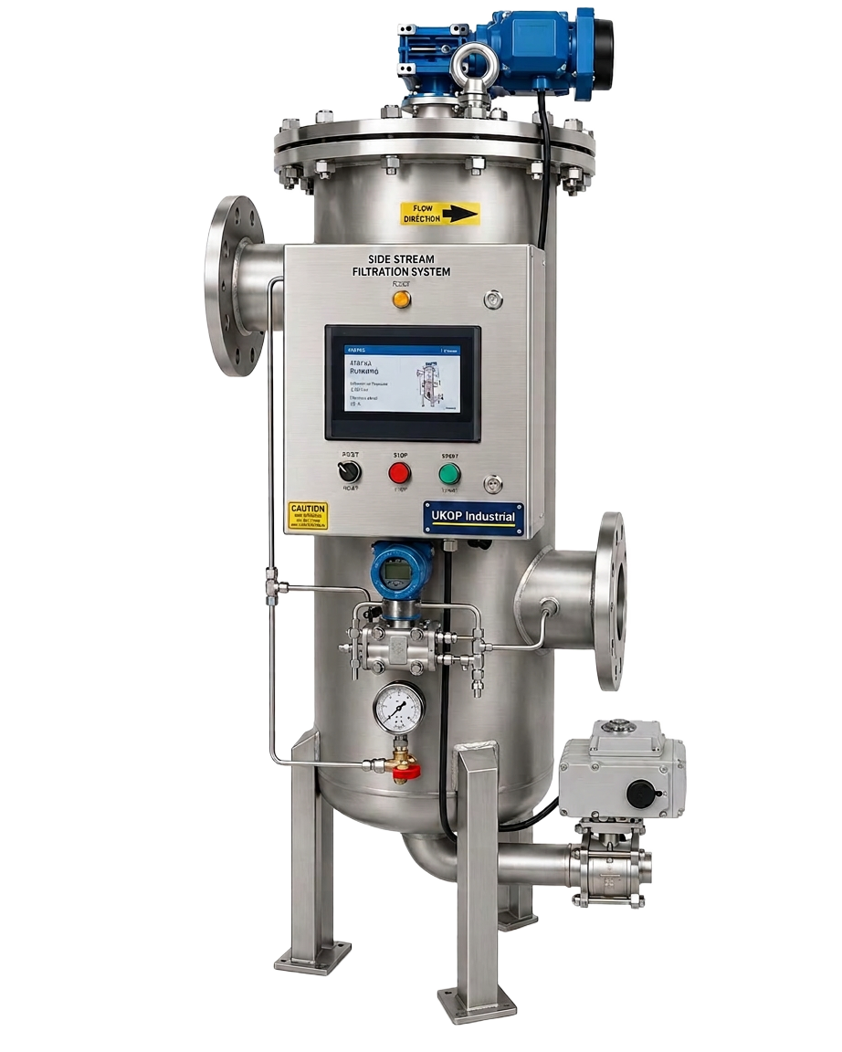
In addition to manual flushing, it is highly recommended to install a side-stream filtration system in conjunction with the header. This ensures that even after the initial pre-commission cleaning, the water remains within the parameters defined by BS 8552 and BSRIA BG50. A side-stream filter helps catch fine particles that a low loss header might miss, thereby protecting the delicate internal components of modern boilers. For large-scale 100kW installations, the combination of a low loss header and effective filtration is the gold standard for plant room reliability. This approach reduces the frequency of chemical dosing and minimizes the risk of blockages in the secondary circuit emitters, such as fan coil units or radiators.
When procurement leads evaluate a 100kw low loss header, they should also consider the ease of air separation. Modern headers are designed to trap micro-bubbles at the top of the vessel, where they can be expelled via an automatic air vent. This is essential for preventing corrosion and cavitation in pumps. UKGP's headers are manufactured with these considerations at the forefront, complying with British manufacturing standards and offering the durability needed for high-pressure commercial heating applications. By choosing a unit with a robust insulation jacket, heat loss is also minimized, meeting the stringent energy performance requirements of current UK Building Regulations Part L.
- Follow BSRIA BG29 for pre-commission cleaning protocols.
- Maintain water chemistry to BS 8552 standards to prevent pitting.
- Consider secondary filtration to protect the header from sludge.
- Use high-quality insulation to comply with Part L energy standards.
Installation Best Practices for M&E Contractors
Installing a 100kw low loss header requires careful planning of the plant room layout to ensure adequate space for maintenance and insulation. The header should be positioned as close to the primary heat source as possible while allowing for straight pipe runs into the vessel to minimize turbulence. M&E contractors should verify that the supporting structure can handle the weight of the header when it is full of water. UKGP’s flanged or threaded options provide flexibility for various pipework materials, whether using traditional steel or modern press-fit systems. Ensuring a leak-free connection is vital, especially when operating at the higher pressures typical of commercial developments.
One common error seen in the field is the incorrect orientation of temperature sensors or the failure to use the sensor pockets provided on the 100kw low loss header. To accurately control the boiler circuit, the primary sensor must be located in a position where it can read the blended supply temperature accurately. UKGP headers are designed with multiple tapping points to accommodate sensors, air vents, and drain valves, ensuring that the engineer has everything needed for a compliant installation. Proper commissioning, including checking the ΔP across the header, will confirm that the hydraulic separation is functioning as intended before handing the system over to the FM team.
Finally, insulation should never be overlooked. A 100kw low loss header has a significant surface area that can become a source of parasitic heat loss if left bare. UKGP provides bespoke insulation jackets that fit snugly around the vessel, ensuring that thermal energy is delivered to the building rather than being wasted in the plant room. With a 2-year warranty and lead times of just 2-3 weeks, UKGP provides a reliable solution for contractors facing tight deadlines. Whether you are using BSP or PN16 connections, these headers are the workhorse of the modern UK plant room, balancing performance with ease of installation.
- Position the header close to boilers to limit primary heat loss.
- Utilise provided sensor pockets for accurate boiler control signals.
- Verify structural support for the operating weight of the vessel.
- Ensure insulation jackets are correctly fitted during the final fix.
Thermal Performance and System Balancing
System balancing is the foundation of a comfortable and efficient building environment. A 100kw low loss header simplifies this process by decoupling the variable flow of the secondary side from the constant flow of the primary side. In a balanced system, the header ensures that each circuit receives the required volume of water without interfering with the flow of others. This is particularly important in multi-zone buildings where demands can change rapidly. By using a header, engineers can prevent issues such as 'dead-heading' pumps or causing flow reversals that confuse BMS sensors and lead to inefficient boiler cycling.
When sizing for a 100kW load, it is worth considering the impact of future-proofing. While a 100kw low loss header is perfect for current requirements, UKGP offers a range up to 2000 kW for larger modular boiler banks. If the building is expected to expand, specifying a slightly larger header now might save significant costs later. However, for a fixed 100kW plant, the DN50/2” header is typically the most cost-effective and space-efficient choice. Its ability to act as a thermal buffer also helps in smoothing out short-term fluctuations in heat demand, providing a more stable setpoint for the building’s climate control systems.
Thermal expansion must also be accounted for in the wider system design. While the header manages hydraulic separation, components like expansion bellows or vessels must be sized to handle the fluid volume changes. The 100kw low loss header itself is built to withstand standard commercial operating pressures, but it is the synergy of all plant room components that ensures long-term reliability. By sourcing from a single reputable UK supplier like UKGP Industrial, M&E contractors can ensure that all components, from the header to the insulation jacket, are compatible and meet the necessary BS EN standards for safety and performance.
- Simplifies hydraulic balancing across multiple heating zones.
- Prevents pump competition and protects boiler heat exchangers.
- Acts as a minor thermal buffer to stabilise supply temperatures.
- Compatible with modular boiler arrangements up to 2000 kW.
Procuring Your 100kw low loss header
For procurement leads and plant room engineers, reliability and availability are the primary concerns when selecting a 100kw low loss header. UKGP Industrial understands the pressures of the UK construction market, offering a 2-3 week lead time to ensure that project milestones are met without delay. Our headers are manufactured to the highest standards, featuring durable finishes and options for both threaded BSP and flanged PN16 connections. This flexibility makes them suitable for a wide variety of commercial applications, from schools and hospitals to office blocks and light industrial units.
The technical superiority of a UKGP 100kw low loss header is backed by a 2-year warranty, giving clients peace of mind that their investment is protected. Included with every unit is a high-performance insulation jacket, designed to meet the thermal requirements of BSRIA and CIBSE recommendations. This not only improves the energy rating of the plant room but also protects maintenance staff from hot surfaces. When requesting a quote, specify your desired connection type and any particular tapping requirements; our team is equipped to provide technical support to ensure the selected model matches your specific flow rate and ΔT targets.
In conclusion, the 100kw low loss header is a foundational component for any medium-sized commercial heating system. It solves the complex problem of hydraulic interference while offering secondary benefits in air and dirt separation. By adhering to the 0.5 m/s velocity rule and ensuring compliance with BSRIA water quality guidelines, engineers can deliver a system that is efficient, quiet, and easy to maintain. Contact UKGP Industrial today for a competitive quote and detailed technical data sheets on our full range of hydraulic separation solutions, including bespoke options for unique plant room configurations.
- Fast 2-3 week lead times for UK-wide delivery.
- Includes high-quality insulation jacket for heat retention.
- Backed by a comprehensive 2-year manufacturer warranty.
- Expert technical support available for sizing and selection.
Frequently asked questions
What is the primary function of a 100kw low loss header?
- It provides hydraulic separation between the primary boiler circuit and secondary heating zones, ensuring constant flow through the boiler regardless of varying secondary demands.
Which connection types are available for the 100kW model?
- UKGP offers these headers with either threaded BSP or PN16 flanged connections to suit different pipework specifications and contractor preferences.
How do I calculate the flow rate for a 100kW header?
- For a standard 20°C temperature drop, use the formula Q = kW / (4.18 × ΔT). This results in a flow rate of approximately 1.2 l/s or 4.3 m³/h.
Does the 100kw low loss header include insulation?
- Yes, all UKGP commercial low loss headers are supplied with a fitted insulation jacket to minimize heat loss and comply with Building Regulations Part L.
Can these headers be used for chilled water systems?
- While primarily used for heating, they can be used for cooling separation; however, different insulation and materials may be required to prevent condensation. Contact our technical team for chilled water applications.