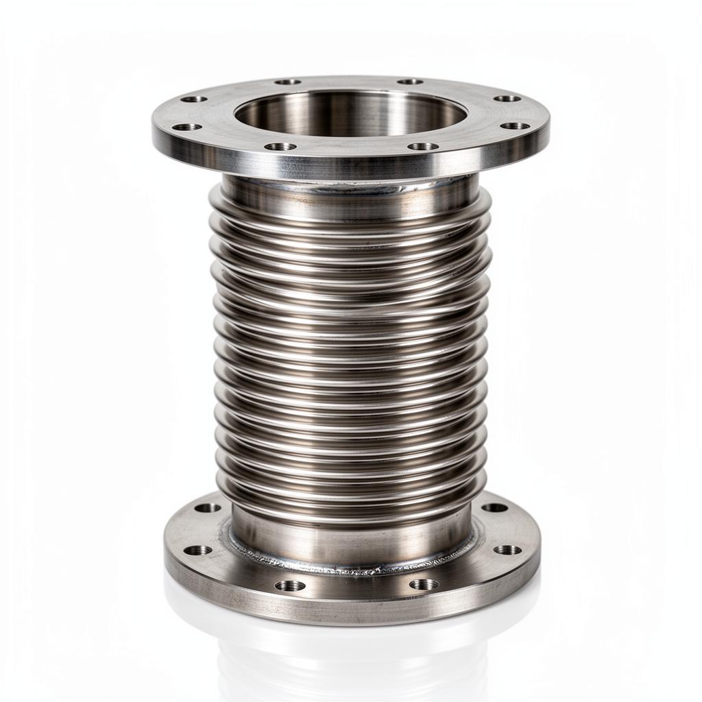
Non Tie-Rod (Untied) Axial Bellows: Characteristics and Risks
Untied expansion bellows, typically referred to as axial joints, are designed to compress or extend along their longitudinal axis. In a standard LPHW or CHW system, as the fluid temperature rises, the pipe expands and the bellows compresses. However, the absence of tie-rods means the internal pressure of the system acts upon the internal cross-sectional area of the bellows (the 'effective area'), creating a significant pressure thrust force. This force attempts to blow the bellows apart and push the pipework away from the joint.
For engineers, the use of untied bellows necessitates the installation of robust main anchors capable of withstanding the sum of the pressure thrust, the spring rate of the bellows, and any frictional forces from pipe guides. Failure to calculate these forces often leads to anchor point failure or 'squirming' of the bellows, where the convolutions deform laterally under pressure. According to EN 14917, the stability of an untied joint is highly dependent on the proximity and quality of the first and second pipe guides.
- Absorbs longitudinal movement along the axis of the pipe only.
- High pressure thrust: Forces generated equal the internal pressure multiplied by the effective area of the convolution.
- Requires heavy-duty main anchors (MA) at all changes of direction.
- Requires precise guiding (BSRIA BG29/21) to prevent squirm and buckling.
Tied Expansion Joints: Restraining Internal Forces
Tied expansion bellows utilize high-tensile steel rods that connect the flanges or weld ends across the convolutions. These rods are designed to take the full load of the internal pressure thrust. Because the rods restrain the joint from extending axially, the pressure thrust is not transmitted to the pipe anchors or the connected equipment, such as pump nozzles or boiler headers. This makes tied units the preferred choice for systems where the structure cannot support the massive loads associated with axial bellows.
It is a common misconception that tied bellows can still absorb axial contraction or expansion. In reality, once the nuts on the tie-rods are tightened (or set with a specific gap for 'limit rods'), the bellows is effectively locked in the axial plane. It can, however, move laterally—where the two ends move parallel to each other but on different centrelines. This movement is facilitated by the use of spherical washers on the tie-rod assemblies, which allow the rods to pivot slightly as the bellows offsets.
- Constraints movements to lateral or angular planes only; axial movement is locked.
- Tie-rods contain the pressure thrust force within the bellows assembly.
- Eliminates the need for massive main anchors; only secondary anchors (SA) are required.
- Ideal for glass-fronted buildings or lightweight structures where anchor loads must be minimised.
The Physics of Pressure Thrust and Anchor Selection
The magnitude of pressure thrust is frequently underestimated by site contractors. For a DN200 bellows operating at 10 bar, the thrust force can exceed 40kN (approximately 4 tonnes). In an untied system, the main anchor must be designed to hold this force securely. If the plant room is situated on a mezzanine or within a modular skid, such loads may skip the structural design limits, leading to potential catastrophic failure of the support steelwork.
By specifying tied expansion joints, the engineer shifts the load from the building's structure to the bellows' tie-rods. In this configuration, the pipe system only 'sees' the force required to deflect the bellows (the lateral spring rate) and the frictional resistance of the guides. This allows for lighter-weight pipe supports and secondary anchors. However, engineers must ensure that UKGP Industrial tied units are correctly oriented, as lateral joints must be installed perpendicular to the direction of the pipe expansion they are intended to absorb.
- EJMA (Expansion Joint Manufacturers Association) calculation methods.
- EN 1092-1 flange rating compatibility.
- BSRIA BG50 requirements for water treatment and corrosion protection.
- PN16 vs PN25 pressure ratings and their impact on rod diameter.
Application Criteria: When to Choose Which Joint
The choice between tied and untied joints is dictated by the piping layout. Untied axial bellows are most efficient in long, straight pipe runs where there is ample space for guiding and sufficient structural mass for main anchors. They are the standard for district heating mains (BS EN 13941) where the pipe is often direct-buried or held in heavy concrete trenches.
Conversely, tied joints are the superior solution for plant room headers and connections to sensitive equipment. In a typical 'Z' bend arrangement, thermal expansion in one leg of the pipe is converted into lateral offset for the tied bellows located in the perpendicular leg. This layout is inherently safer as it does not rely on the integrity of heavy anchors to prevent the pipe from 'telescoping' out of its supports. When using UKGP Industrial flanged expansion bellows, engineers should verify that the tie-rod lugs are integral to the flange or properly welded to ensure load path continuity.
- Axial bellows: Install in long straight runs with guides at 4D and 14D distances.
- Tied bellows: Best utilized at 'Z' bends or 'L' bends in the piping layout.
- Universal tied joints: Feature two bellows sections to allow for greater lateral offset.
Installation Pitfalls and Maintenance according to BS EN Standards
One of the most frequent errors in UK HVAC installations is the removal of tie-rods by site contractors who mistake them for temporary shipping bars. Unless the rods are painted a specific 'shipping' colour (usually yellow) and clearly labelled for removal, they are structural components of the joint. Removing them from a lateral joint converts it into an untied axial joint, often without the necessary main anchors in place, leading to immediate failure upon pressurisation.
Maintenance regimes according to BSRIA BG50 should include a visual inspection of the bellows convolutions and the tie-rod assembly. For tied joints, engineers must check for signs of thread galling or bending in the rods, which may indicate that the system is expanding beyond its design limit. In untied systems, the focus must be on the pipe guides; if the pipe is binding in the guides, it will transmit eccentric loads to the bellows, significantly reducing its fatigue life and potentially causing a breach of the EN 14917 pressure boundary.
- Improper pre-setting of lateral offsets.
- Over-tightening tie-rod nuts, preventing spherical washer movement.
- Removing tie-rods after installation (thinking they are shipping bolts).
- Inadequate guiding leading to bellows squirm in untied systems.
Summary of Specification Priorities
Selecting the correct bellows requires a holistic view of the piping system. Untied axial bellows are simple but place the burden of safety on the anchors and guides. Tied lateral bellows are more complex to manufacture but offer a self-contained solution for pressure thrust, protecting the wider building infrastructure. For most modern UK commercial developments, the trend is toward tied solutions to mitigate the risks associated with structural load limits.
Ultimately, the specification must reference the correct British and European standards. Whether opting for a standard untied unit or a complex tied universal joint, ensuring the material compatibility—such as using UKGP Industrial stainless steel units for corrosive environments—is as vital as the mechanical configuration. Consulting the EJMA standards for bellows life-cycle (typically 1000 to 3000 cycles for HVAC) will further ensure the longevity of the installation.
- Total calculated thermal expansion (mm).
- Maximum working pressure (bar) and test pressure.
- Space constraints for anchoring and guiding.
- Conveyed medium (AISI 316L for potable water or EPDM for LPHW).
Frequently asked questions
Can I use tie-rods on an axial expansion bellows to make it 'safer'?
- No. Once tie-rods are installed, they prevent the bellows from absorbing axial movement. A tied unit is strictly for lateral or angular offset. Replacing an axial bellows with a tied unit will transfer all thermal expansion back into the pipework and equipment nozzles.
What are the maintenance requirements for tied bellows?
- Tie-rods must be inspected for thread stripping, nut 'backing off', and deformation. The spherical washers must be lubricated and free to move to ensure the tie-rods do not lock up the joint and prevent the intended lateral flexibility.
Is there a way to have tie-rods and still accommodate axial movement?
- In high-pressure systems where main anchors are impossible to install, pressure-balanced expansion joints are used. These use tie-rods to link the working bellows to a balancing bellows, neutralising pressure thrust while still allowing axial movement.
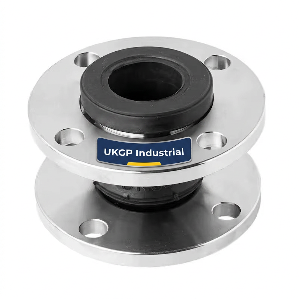
Are the requirements different for rubber vs metal bellows?
- While rubber bellows often include tie-rods (limit rods) as standard to prevent over-extension, metal bellows (EN 14917) require specific engineering of the rods to act as the primary constraint against internal pressure thrust.