Regulatory Framework and Compliance Standards
In the UK, the specification of gas solenoid valves is governed by a strict hierarchy of standards. The primary performance standard is BS EN 161, which classifies valves based on their sealing integrity and operational life. For most commercial boiler house applications, a Class A, Group 2 valve is the mandatory requirement. This ensures that the valve can provide a tight shut-off against the maximum system pressure and operate reliably for thousands of cycles.
Installers must also adhere to the Institution of Gas Engineers and Managers (IGEM) standards, specifically IGEM/UP/2 Edition 3. This document outlines the requirements for pipework and the positioning of isolation valves. It stipulates that safety shut-off valves must be capable of closing within less than one second of a signal being received, a requirement that standard solenoid valves are designed to meet, unlike slower-acting motorised butterfly valves.
For specialist environments such as commercial kitchens, BS 6173 requires that the gas supply be interlocked with the ventilation system. This typically necessitates a normally-closed solenoid valve that will only open when airflow is proven. Failure to specify a valve that meets these criteria not only compromises safety but also leads to non-compliance during Gas Safe inspections and insurance audits.
- BS EN 161: Automatic shut-off valves for gas burners and gas appliances.
- IGEM/UP/2: Installation of pipework on industrial and commercial premises.
- BS 6173: Professional catering manual for gas safety interlocks.
- Gas Safety (Installation and Use) Regulations 1998.
Valve Types: Automatic vs. Manual Reset
The choice between automatic and manual reset solenoid valves depends entirely on the downstream application and the level of risk management required. Automatic reset valves are predominantly used in boiler houses where the plant is designed to restart automatically after a momentary power dip. These valves are often controlled by a Building Management System (BMS) or a dedicated gas pressure proving system.
Manual reset valves are a critical safety feature in environments where gas flow must not be restored without an operator first verifying that conditions are safe. In commercial kitchens or laboratories, a manual reset valve prevents gas from flowing into an unattended space if the power returns after a trip. These valves feature a mechanical 'pull-lever' or button that must be engaged by a technician to re-seat the internal mechanism and allow the magnetic field of the coil to hold the valve open.
Building services engineers must also consider whether 'slow-opening' characteristics are required. In larger industrial burners, high-capacity solenoid valves with an adjustable hydraulic damper prevent pressure surges (gas hammer) in the pipework. These valves typically open rapidly for the first few millimetres to satisfy pilot flames, then slowly ramp up to full flow over 10 to 30 seconds.
- Automatic Reset: Re-opens as soon as power is restored to the coil.
- Manual Reset: Requires a physical pull-up or button press to re-open after power restoration.
- Slow Opening: Uses a hydraulic damper to ramp up gas flow over several seconds.
Sizing and Flow Dynamics for Gas Systems
Sizing a gas solenoid valve based solely on pipe diameter is a common error that can lead to excessive pressure drops or erratic burner performance. Engineers must calculate the required flow rate in m³/h (cubic metres per hour) based on the total kW rating of the connected appliances. This figure, combined with the available inlet pressure and the maximum allowable pressure drop across the valve, determines the required Kv value.
Typical gas systems operate at low pressures (21mbar for natural gas), meaning even a small pressure drop across a poorly sized valve can cause flame instability at the burner. For most plant-room specifications, a pressure drop of no more than 1mbar across the solenoid valve at peak demand is targeted. This ensures that downstream regulators have sufficient head to maintain steady pressure during high-fire operations.
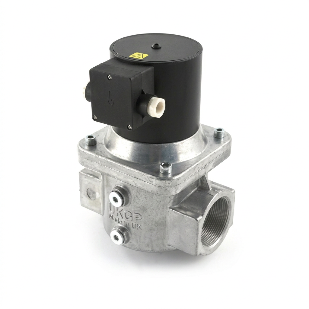
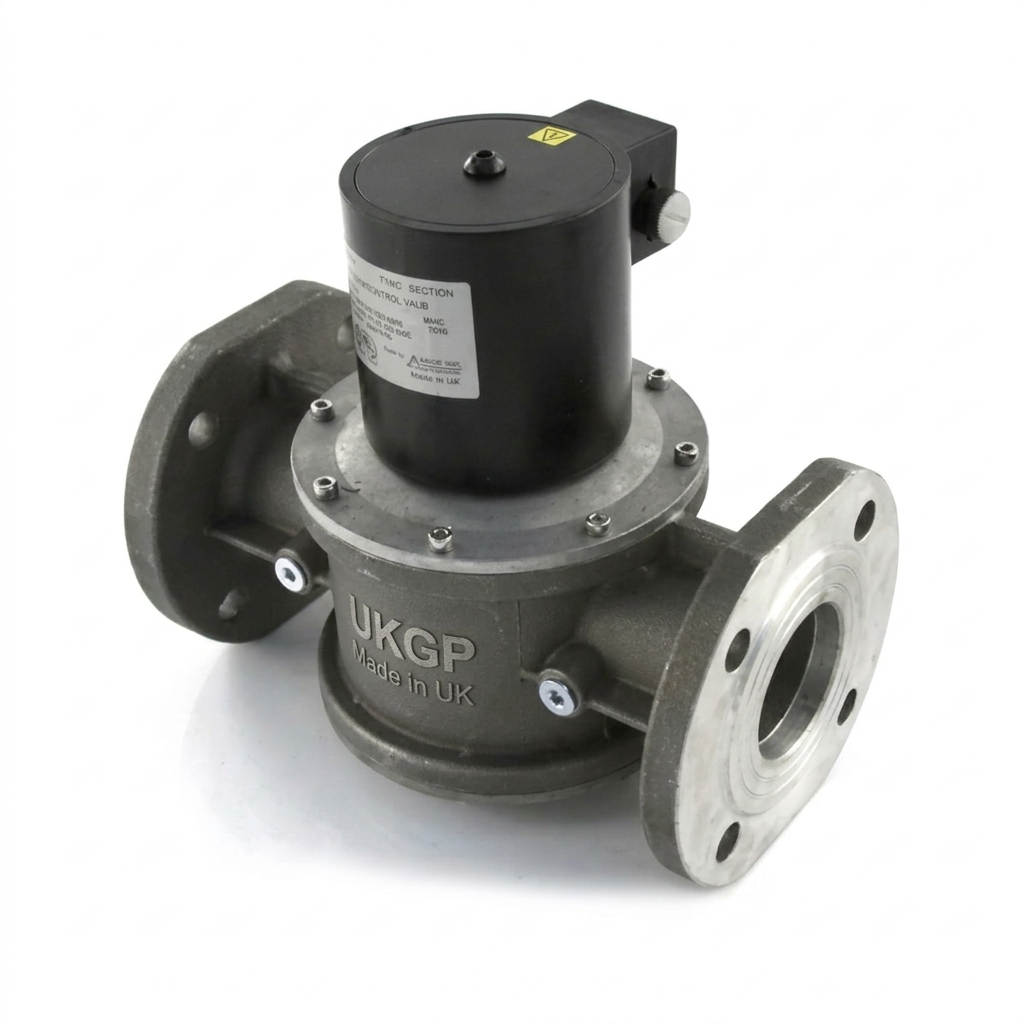
The UKGP Industrial range of gas solenoid valves provides detailed flow charts to assist in this selection process. When transitioning from 50mm screwed pipework to larger flanged sections, it is vital to ensure that the valve’s Maximum Operating Pressure (MOP) matches the system’s design. For example, some industrial sites operate 2 bar or 5 bar gas mains, which require high-pressure solenoid valves rather than standard 360mbar variants.
- Screwed connections (BSP) for diameters 15mm to 50mm (1/2" to 2").
- Flanged connections (PN16) for diameters 65mm to 300mm.
- Flow rate (m³/h) at a specific pressure drop (typically 0.5mbar to 1mbar).
Material Science and Valve Construction
In UK commercial heating, the majority of gas solenoid valves utilize high-grade die-cast aluminium bodies. Aluminium offers an excellent strength-to-weight ratio and is resistant to the corrosive trace elements sometimes found in natural gas or LPG. For more aggressive environments or process gas applications involving 'dirty' gas (e.g., biogas), engineers may need to specify stainless steel or specially coated valves to prevent premature degradation of the valve seat.
The internal seals are arguably the most important component for long-term reliability. Nitrile rubber (NBR) or Viton (FKM) are standard, providing the necessary resilience to maintain a gas-tight seal over thousands of cycles. It is critical to ensure that these seals are compatible with the gas type; for instance, town gas or specific LPG blends may require different elastomeric compounds compared to standard North Sea natural gas.
The solenoid coil itself is the only moving part's driver. In UK plant rooms, coils are typically rated for 230V AC, although 24V DC and 110V AC variants are common in industrial control panels. A high-quality valve will feature an IP65 or IP67 rated coil housing, protecting the electrical internals from water ingress and dust, which is vital in basements or rooftop plant rooms where condensation can be prevalent.
- Internal pilot-operated valves vs. direct-acting valves.
- Aluminium alloy vs. cast iron or brass bodies.
- IP65 rated coils for boiler houses with high humidity or dust levels.
Electrical Integration and BMS Interlocking
Modern building services design requires total integration of the gas safety system with the Building Management System (BMS). A key feature offered on high-specification valves is the Closed Position Indicator (CPI) switch. This is a volt-free micro-switch that provides positive feedback to the BMS, confirming that the valve is physically closed. This is often used in sequencing logic or as a prerequisite for burner ignition sequences to ensure no leak-by is present.
The wiring of the solenoid valve must always be 'fail-safe'. This means the valve is held open by a continuous electrical signal. Any interruption to this signal—whether from a gas detector, fire alarm, low-pressure switch, or manual emergency stop button—will result in the immediate closure of the valve. In the UK, it is standard practice to wire these safety devices in a series loop (the 'break-to-stop' circuit) to ensure that a fault in any single device isolates the gas.
Current surges during the activation of large solenoid coils can cause interference in sensitive control electronics. Specifying valves with filtered coils or using interposing relays within the control panel can mitigate these issues. Furthermore, for installations in hazardous areas (ATEX zones), specifically certified explosion-proof coils and enclosures must be used, although this is rarely a requirement for standard commercial boiler houses.
- Visual indicators (CPI - Closed Position Indicator).
- BMS integration for remote status monitoring.
- Emergency stop (E-Stop) loop integration.
Installation Best Practices and BSRIA Guidelines微
Proper installation is as crucial as the specification itself. According to BSRIA BG29/21 and BG50, any gas line should be thoroughly purged and cleaned before the installation of sensitive control valves. Debris such as pipe scale, swarf, or excess jointing compound can lodge in the valve seat, preventing a full seal and causing 'let-by'—a major safety hazard and a frequent cause of failed gas inspections.
An upstream gas filter or strainer is mandatory. This protects the precision-machined internals of the solenoid valve from particulates. The strainer should be serviced regularly as part of the annual maintenance schedule. Most solenoid valves are designed for horizontal installation with the coil facing upwards; installing them upside down or on vertical runs can lead to premature mechanical wear or the accumulation of moisture within the coil housing.
Space for maintenance must be allowed. This sounds rudimentary, but a valve tucked into a corner where the coil cannot be removed for replacement is a common oversight. There should be sufficient clearance for a technician to test for tight shut-off using a U-gauge or electronic leak detector at the pressure test points usually provided on the inlet and outlet of the valve body.
- Inlet strainer/filter to protect the valve seat.
- Orientation: horizontal or vertical mounting restrictions.
- Distance from burners and regulators as per IGEM/UP/2.
Specialist Applications: LPG and High-Pressure Systems
While natural gas is the most common fuel in UK commercial properties, LPG (Propane/Butane) applications require specific considerations. LPG is more dense than air and has a higher calorific value, often requiring smaller valve orifices but higher pressure ratings. Because LPG is stored in tanks at higher pressures, the solenoid valves used in the first or second stage of regulation must be rated for significantly higher MOPs than those used at the burner.
In industrial sectors where gas boosters are used to increase delivery pressure, the solenoid valve must be interlocked with the booster’s operation. If the booster fails, the solenoid valve should close to prevent low-pressure gas from reaching burners not designed for it. High-pressure valves (up to 6 bar) are often constructed with more robust castings and heavy-duty springs to ensure they can overcome the internal forces of the high-velocity gas stream during closure.
For town gas or manufactured gas systems, which may still exist in some older industrial quarters or specific process plants, the chemical composition of the gas must be checked against the valve’s seal material. Some older gas types have higher moisture or sulphur content, which can degrade standard NBR seals rapidly. UKGP Industrial advisors can provide guidance on seal compatibility for these niche applications.
- LPG (Liquefied Petroleum Gas) vs. Natural Gas.
- Booster pump interlocks.
- High-pressure industrial process lines.
Summary Checklist for Specification
When finalising a specification for a gas solenoid valve, the engineer should consolidate the requirements into a clear technical data sheet for the procurement team. The primary data points are: Pipe Size (BSP or PN16), Gas Type, Maximum Operating Pressure (MOP), Flow Rate (m³/h), Voltage (230V/110V/24V), and Reset Type. Adding the requirement for a CPI switch is highly recommended for any system monitored by a BMS.
Verify that the chosen valve carries the UKCA or CE mark and is certified to EN 161. In the UK’s post-Brexit regulatory landscape, ensures that the UKCA marking is valid for the product category. Consult the manufacturer’s flow-pressure charts to ensure the pressure drop at peak load does not exceed the project design parameters, typically sub-1mbar for low-pressure systems.
Finally, consider the long-term maintenance of the plant. Specifying a commonly used, high-reliability brand like UKGP Industrial ensures that replacement coils and seal kits remain available throughout the life of the plant. This reduces downtime and ensures that the facility remains compliant with the Safety-Related Systems requirements of current UK gas legislation.
- Calculation of Total Gas Demand (TGD).
- Assessment of environmental conditions (ATEX, IP rating).
- Selection of reset mode (Auto vs. Manual).
Frequently asked questions
Why is 'normally-closed' the standard for safety shut-off valves?
- Normally-closed valves require power to remain open. In the event of a power failure or an emergency signal (from a gas detector or fire alarm), the internal spring immediately forces the valve shut, isolating the gas supply. Manual reset versions require an operator to physically intervene before gas can flow again, preventing accidental re-ignition after a fault.
What is the importance of the Maximum Operating Pressure (MOP) rating?
- Maximum Operating Pressure (MOP) defines the safe limit for a valve. In commercial UK plant rooms, 200mbar or 360mbar variants are common for low-pressure systems. For industrial applications or booster outlets, 6bar valves are required. Exceeding the MOP can lead to valve failure or leak-by.
What is the difference between Class A and Class B valves?
- Class A valves (Group 2) are high-integrity safety shut-off valves required for the majority of UK gas installations. They must meet stringent closure times and internal leakage rates defined by BS EN 161. Class B or C valves are generally not permitted for primary safety shut-off duties in UK boiler houses.
How often should gas solenoid valves be serviced?
- Valves should be checked annually for tight shut-off (leak-by) and response time. The solenoid coil should be inspected for signs of overheating or degradation. In systems following BSRIA BG50, ensuring gas quality is high and that the upstream strainer is clean is essential for valve longevity.