Anatomy of a Normally-Closed Gas Solenoid Valve
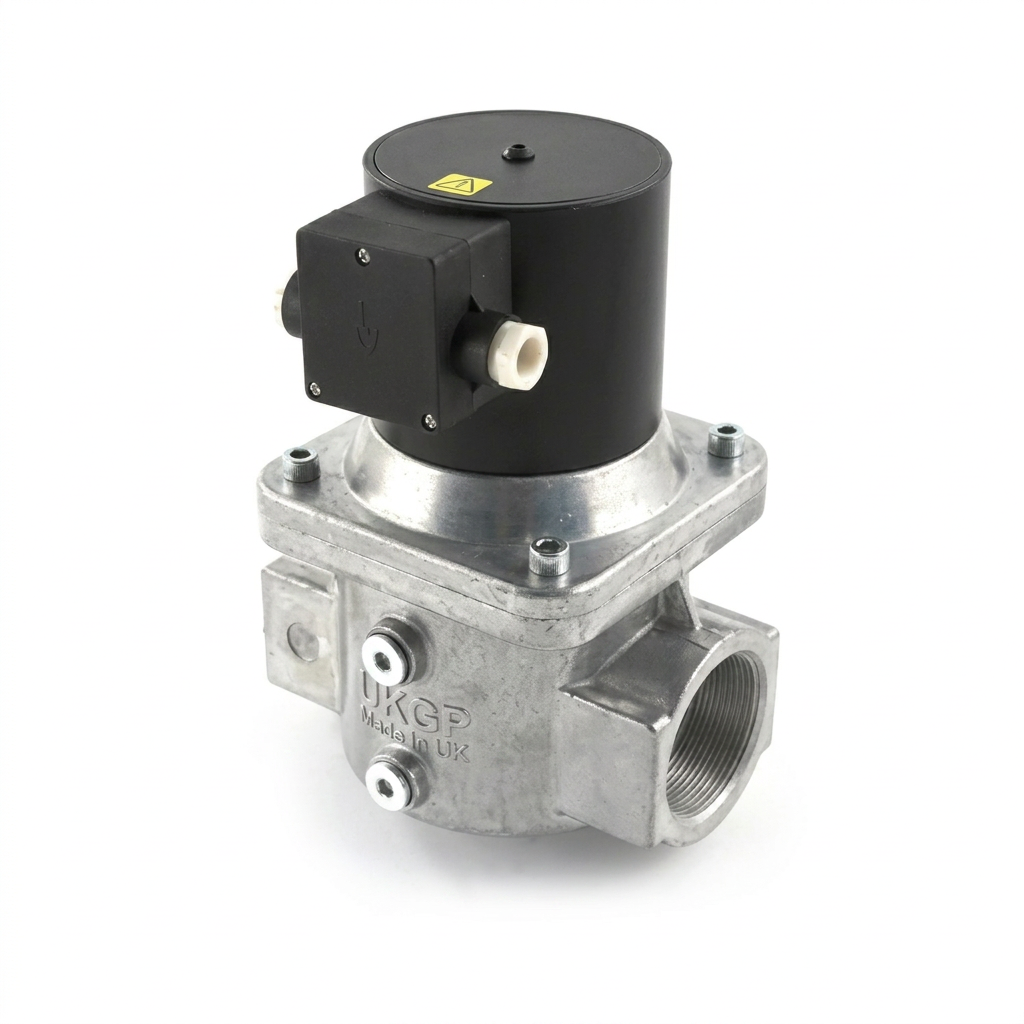
The standard automatic-reset gas solenoid valve used in UK boiler rooms is a direct-acting or pilot-operated electromechanical device. At its core, the valve comprises a copper wire coil wrapped around a plunger tube. When an electrical current (typically 230V AC or 24V DC) passes through the coil, it generates a magnetic field. This field pulls the internal plunger upwards, overcoming the downward force of the return spring and lifting the sealing disc off the valve seat.
Unlike general-purpose water solenoids, gas safety valves must adhere to stringent sealing requirements. The 'normally closed' (NC) designation is a fundamental safety feature: the valve requires a constant electrical signal to remain in the 'open' state. If the power supply is interrupted—whether by a fire alarm trigger, a gas detection panel, or a simple power failure—the magnetic field collapses instantly. The internal return spring then forces the plunger back down, providing a bubble-tight seal against the gas flow.
UKGP Industrial valves are typically constructed from die-cast aluminium alloys or brass, designed to handle the chemical properties of Natural Gas (Methane), LPG (Propane/Butane), and Town Gas. The internal seals are usually Viton or NBR, selected for their resistance to hydrocarbons and their ability to maintain integrity across a wide temperature range, typically -15°C to +60°C.
- Coil: The electromagnetic assembly that converts electrical energy into linear motion.
- Plunger (Core): A ferromagnetic rod that moves within the sleeve.
- Return Spring: The safety mechanism that forces the valve closed when de-energised.
- Main Orifice and Disc: The sealing surface that arrests the gas flow.
- Manual Flow Adjustment: Often found on the base of the valve to limit maximum throughput.
Compliance with EN 161 and BS Standards
In the UK, gas solenoid valves must be CE or UKCA marked and certified to EN 161. This standard governs 'Automatic shut-off valves for gas burners and gas appliances.' Under EN 161, valves are categorised into 'Classes' based on their sealing performance and 'Groups' based on their mechanical strength. Most commercial plant room applications require Class A, Group 2 valves, which represent the highest tier of safety and reliability.
The Gas Safety (Installation and Use) Regulations 1998, along with IGEM/UP/2 (Gas installation pipework, boosters and compressors in industrial and commercial premises), dictate where and how these valves are installed. For instance, any gas line entering a building with a volume greater than a specific threshold or serving specific plant must have a means of automatic isolation. The solenoid valve serves as this primary safety barrier, often interlocked with the boiler's flame failure system.
Furthermore, for commercial catering installations, BS 6173 requires the presence of a gas-to-ventilation interlock. This ensures that the solenoid valve cannot open (and thus provide gas to the appliances) unless the mechanical ventilation system is proven to be operational. This prevents the build-up of combustion products (CO and CO2) in the kitchen environment.
- Class A: High-pressure capability with maximum leakage rates defined by EN 161.
- Group 2: High mechanical strength for industrial environments.
- Pmax: The maximum inlet pressure the valve can safely contain.
Electromagnetic Principles and Actuation
The physics behind gas valve actuation relies on Ampère's circuital law. When the BMS sends a signal to the valve's terminal box, the resulting current creates a concentrated magnetic flux within the solenoid sleeve. This flux acts upon the ferromagnetic plunger. In a 'fast-opening' valve, this process occurs in less than one second, providing immediate gas flow to the burner train.
However, in many large-scale UK industrial applications, 'slow-opening' valves are preferred. These valves incorporate a hydraulic damper or a bypass mechanism that allows the valve to open gradually over a period of 1 up to 30 seconds. This is critical for preventing 'lock-up' of downstream gas pressure regulators and ensuring a smooth ignition sequence for high-output boilers (typically those exceeding 1mW).
The 'automatic reset' functionality means that once the electrical signal is restored, the valve will automatically re-energise and open. While this is convenient for remote plant rooms, engineers must ensure that this does not create a hazard. If a manual intervention is required for safety reasons (such as after a gas leak is detected), a 'Manual Reset' solenoid should be specified instead, or the control logic should be programmed at the BMS level to require a manual 'ack' before re-energising the circuit.
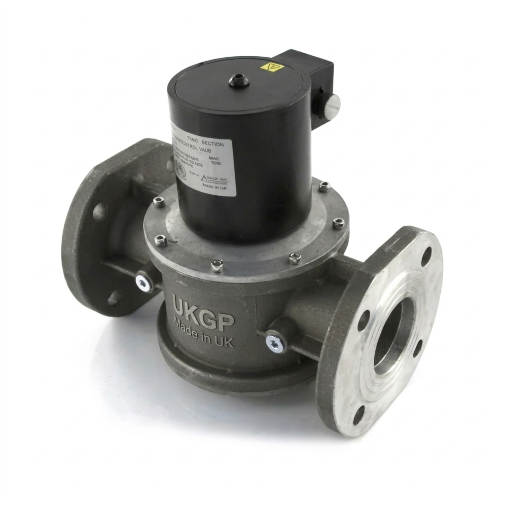
- Direct-Acting: The solenoid force directly lifts the valve disc. Common for smaller line sizes (up to 2").
- Pilot-Operated: Uses the pressure of the gas itself to help open the valve. Common for high-flow industrial applications.
- Two-Stage Opening: A slow-opening variant used to prevent pressure surges and 'nuisance trips' on downstream regulators.
Pressure Considerations and Sizing
Sizing a gas solenoid valve is not as simple as matching the pipe diameter. An undersized valve will introduce an excessive pressure drop (ΔP) across the seat, which can starvation the burner and lead to combustion instability. Conversely, an oversized valve may be unnecessarily expensive and can, in some pilot-operated models, fail to open correctly if the minimum differential pressure isn't met.
When specifying a valve, the engineer must calculate the volume flow rate (m³/h) at the peak demand of all connected appliances. Most UK natural gas systems operate at a nominal 21 mbar at the meter, but the pressure at the valve may be lower due to friction losses in the pipework. High-quality valves, such as those in the UKGP Industrial range, provide flow curves that allow engineers to select a valve that keeps the pressure drop below the recommended 1 mbar threshold for low-pressure systems.
It is also vital to consider the 'Maximum Operating Pressure' (MOP). While a valve might be rated for 500 mbar, using it on a 2-bar medium-pressure feed will result in a failure of the solenoid to lift the plunger against the high inlet pressure, or worse, a mechanical failure of the seals. Always verify the incoming gas pressure before selection.
- 0.5 bar (500 mbar): Standard for most commercial low-pressure systems.
- 1 bar to 6 bar: Specified for medium-pressure industrial feeds and gas booster outlets.
Electrical Integration and Interlocking
Modern gas solenoid valves often feature 'Visual Position Indication' or 'Closed Position Indicator (CPI)' switches. These are auxiliary micro-switches that provide a volt-free contact back to the BMS to confirm the physical state of the valve (open or closed). This is a critical requirement in multi-stage ignition sequences where the burner controller must verify that the safety shut-off valve is fully closed before attempting a pre-purge.
The electrical enclosure or 'plug' of the valve is typically rated to IP65, protecting it from dust and moisture in plant room environments. When wiring these units, it is essential to use heat-resistant cable if the valve is located near the boiler flue or heat exchanger. Standard PVC cable can degrade over time, leading to short circuits and unintended valve closures.
In any safety-critical application, the valve should be wired in series with the entire safety chain. This includes the high/low gas pressure switches, the boiler's limit thermostat, and any emergency stop (E-Stop) buttons. If any link in this chain breaks, the solenoid loses power and the gas supply is immediately isolated.
- BMS Interlock: Connection to the building management system for remote monitoring.
- Gas Detection: Integration with CH4 or CO sensors.
- Emergency Stop Buttons: Physical 'mushroom' switches located at exits.
Installation Best Practices and BSRIA Guidelines
Installation should always be carried out by a Gas Safe Registered engineer qualified for non-domestic work. One of the most common causes of solenoid valve failure is the ingress of 'black dust' or welding slag from the pipework. This debris settles on the valve seat, preventing a tight seal and causing 'let-by.' To prevent this, a gas filter (complying with DIN 3386) must be installed immediately upstream of the solenoid valve.
BSRIA BG29/21 and BG50 provide guidance on the pre-commissioning cleaning and maintenance of building services systems. For gas lines, this involves ensuring the pipework is purged of air and debris before the valve is energised. During the installation phase, the valve should be protected from paint overspray and vibration, both of which can impair the movement of the internal plunger.
Orientation is also a factor. While many modern solenoid valves are designed to operate in both horizontal and vertical pipe runs, the solenoid coil itself should ideally be positioned upright (at the 12 o'clock position). This prevents the accumulation of moisture and particulate matter within the plunger tube, which could otherwise cause the valve to stick or the coil to burn out prematurely due to heat build-up.
- Horizontal vs Vertical: Most valves can be mounted in either orientation, but the coil should never point downwards.
- Flow Direction: Noted by an arrow on the valve body; installing in reverse prevents the valve from sealing.
- Debris Protection: The importance of upstream gas filters.
Maintenance and Operational Lifespan
A high-quality gas solenoid valve is a low-maintenance device, but it is not a 'fit and forget' component. Over time, the internal return spring can lose tension, or the elastomeric seals can harden, especially in high-temperature environments. Periodic inspection involves checking the coil for signs of overheating (discolouration) and ensuring that the electrical connections are secure and free from corrosion.
Functional testing is a mandatory part of annual gas safety inspections in the UK. This involves 'tripping' the valve via the E-stop or BMS and using a pressure gauge (U-gauge or digital manometer) to ensure that the gas pressure downstream of the valve drops to zero and remains there. If the pressure holds or rises, the valve is passing gas (let-by) and must be repaired or replaced immediately.
A common issue encountered by FMs is 'solenoid hum'—an audible 50Hz buzzing coming from the coil. This is frequently caused by a small amount of dust between the plunger and the fixed core, which prevents the magnetic circuit from fully closing. While it might seem like a minor nuisance, the vibration can lead to premature mechanical wear and eventual coil burnout. Cleaning the plunger tube or replacing the coil assembly usually resolves the issue.
- Solenoid Hum: Often caused by dirt in the plunger tube or incorrect voltage.
- Coil Failure: Can occur due to voltage spikes or lack of ventilation around the coil.
- Internal Leakage: Usually a sign of seat damage or debris.
Specifying for Long-Term Reliability
When specifying gas solenoid valves for UK projects, engineers should look beyond the initial purchase price and consider the Total Cost of Ownership (TCO). This includes the availability of replacement coils and the ease of access for testing. A valve that allows for the attachment of a 'closed position indicator' (CPI) switch, even if not required initially, provides future-proofing for later BMS upgrades.
The environment of the plant room should also dictate the materials. In coastal areas or industrial sites with corrosive atmospheres, valves with specialised coatings or stainless steel components may be required. However, for the vast majority of UK heating applications, the standard aluminium-bodied Class A valve remains the industry benchmark for safety and performance.
Finally, always ensure that the valve is matched to the specific gas type. While natural gas is the most common, LPG systems operate at higher pressures and have different density characteristics, requiring slightly different sizing calculations. By following IGEM/UP/2 and choosing certified components like those from UKGP Industrial, engineers can ensure their gas safety systems provide robust protection for the life of the building.
- Safety first: Ensuring the gas line is isolated before maintenance.
- Future-proofing: Selecting valves with spare porting for pressure gauges.
Frequently asked questions
What does 'normally closed' mean in the context of gas safety?
- A 'normally closed' valve requires continuous electrical power to remain open. In the event of a power cut, fire alarm activation, or BMS lockout, the valve fails-safe to the closed position via spring force.
What is the difference between an automatic and manual reset gas valve?
- While both are Class A safety shut-off valves, automatic reset valves re-open as soon as power is restored. Manual reset valves require a technician to physically reset the valve after a trip, providing an extra layer of safety to ensure the cause of the shutdown is investigated.
Do I need a gas interlock system for a commercial kitchen?
- A Gas Interlock System is mandatory under BS 6173 for commercial kitchens. It ensures the gas solenoid valve only opens when the extraction and supply fans are proven to be operating via air pressure switches.
How do I size a gas solenoid valve correctly?
- The valve should be oversized for the pipework only if pressure drop calculations demand it. Typically, the valve is sized based on the maximum flow rate (m³/h) and the allowable pressure drop (usually <1 mbar), rather than just matching the pipe diameter.
How often should a gas solenoid valve be serviced?
- Under BSRIA and IGEM guidelines, valves should be visual inspected monthly and functionally tested (proving tight shut-off) every 6-12 months as part of the annual gas safety check.